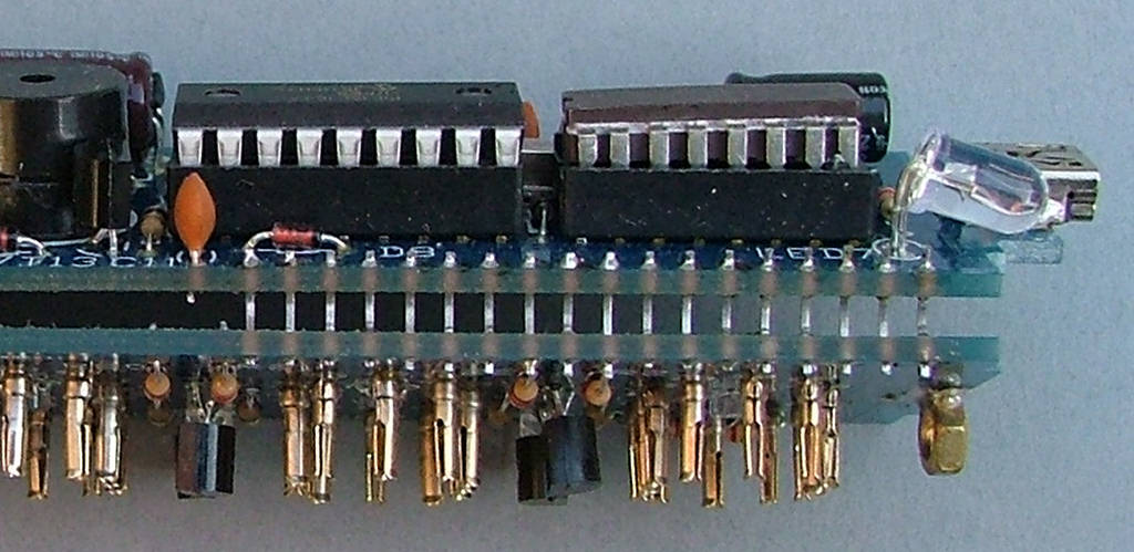
Strip the outer insulation from the USB cable and cut off the 2 wires that ARE NOT red and black. Strip the ends of the red and black wires then tin them.
Feed the wires through one of the large holes in the PCB marked for SK1
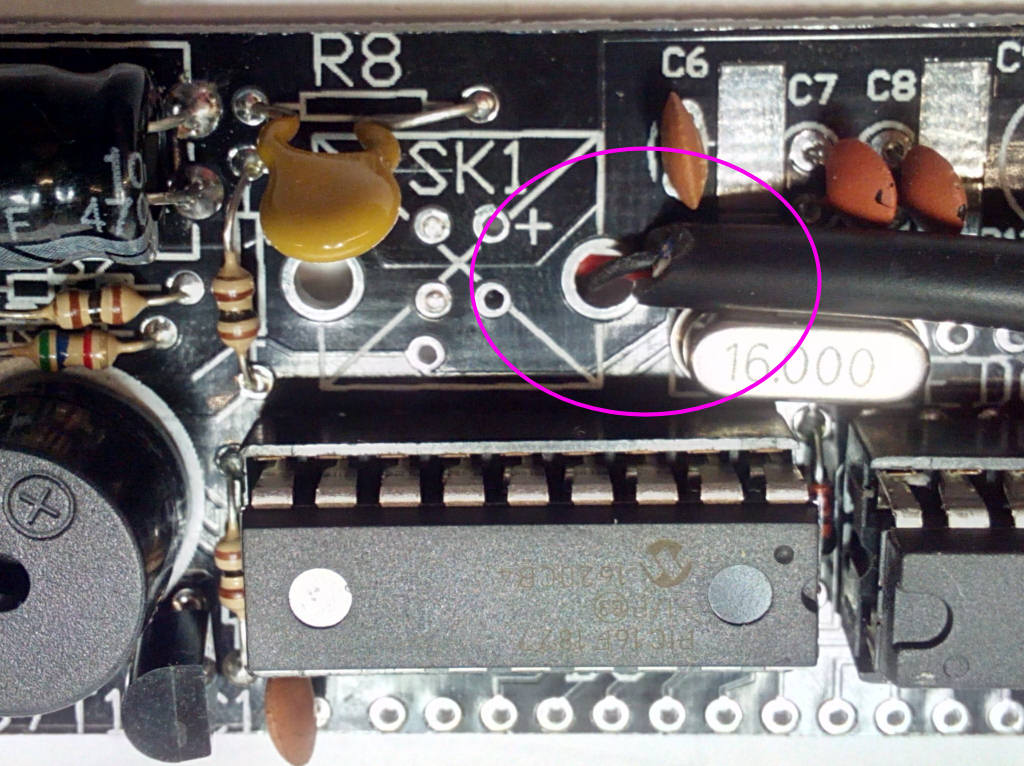
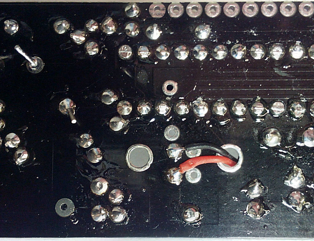
Solder the 2 wires onto the pads shown here - the red wire connects to R8 and the black wire to ground.
Now it's time to try power for the first time. Connect a multimeter on a current range (about 0-500mA) between the pads where R8 will be - this is just to the right of C5. Connect the - black lead to the left pad and the + red lead to the right pad.
Plug in the USB power supply and switch on.
You should have a reading of a few mA which rapidly drops to less than 1mA as C5 charges. Switch off and disconnect everything. If the test was OK move onto the next stage, if not check for solder bridges. If there was no reading at all make sure your meter is working and connected correctly, fluaty meter fuses are a commpn problem here.
