Connect the board to your power supply again and repeat the current test. It should still be about 6mA.
Check the voltage across the two diodes marked here:
It should be about 2.5V, if not check for shorted tracks and solder bridges around the transistors.
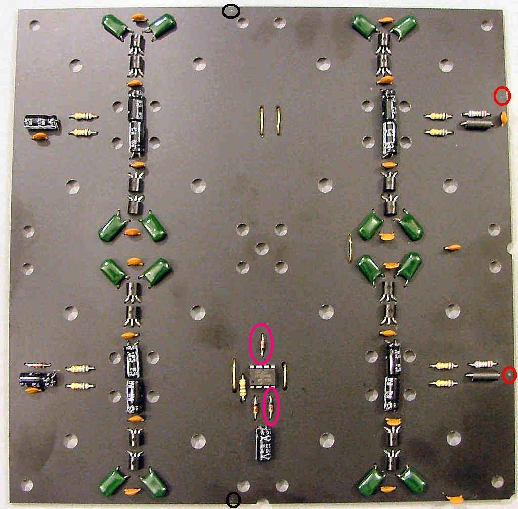
If you've made it this far you should have a completed and working board ready for the driver coils. Repeat with the other 2 boards and you should now know which parts still need to be fitted to the partly built board.
Board PCB
Assembly instructions for the V1 chessboard.
Return to “Assembly instructions”
Jump to
- Timelord Kits
- ↳ Plasma button of Doooom
- ↳ Nixie thermometer V1
- ↳ Assembly instructions for the Thinkgeek nixie thermometer
- ↳ Nixie chessboards
- ↳ Nixie Chessboard V1
- ↳ Assembly instructions
- ↳ Nixie Chessboard V1.5
- ↳ Assembly instructions
- ↳ Nixie Chessboard V1.6
- ↳ Assembly Instructions
- ↳ Nixie OXO board V1
- ↳ OXO board assembly instructions
- ↳ 5-tube nixie clocks
- ↳ IN-14 V1 5-tube nixie clock
- ↳ Assembly Instructions for the IN-14 5-tube clock
- ↳ Mad science Nixie clock - TBA
- ↳ The Coppertop IN-8-2 kit
- ↳ Assembly instructions for the Coppertop clock kit
- ↳ The Cylinder IN-12 V3 Clock
- ↳ Assembly instructions for the Cylinder V3 clock kit
- ↳ Time Flies
- ↳ Setup and operating help
- ↳ Assembly instructions - kit version
- ↳ 1 - GPS mouse
- ↳ 2 - Power controller
- ↳ 3 - Levitation base
- ↳ 4 - Clock modules
- ↳ Beacon
- ↳ Relay 5-tube
- General discussion
- ↳ General discussion
- ↳ Gallery