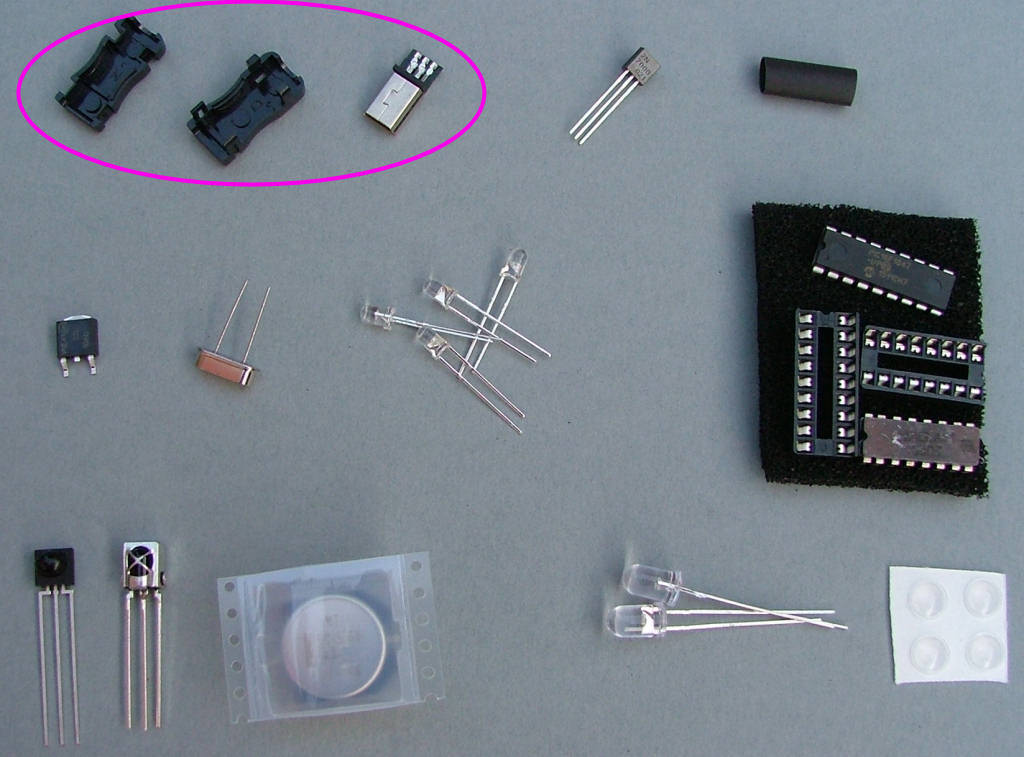
No longer supplied, left here for reference only.
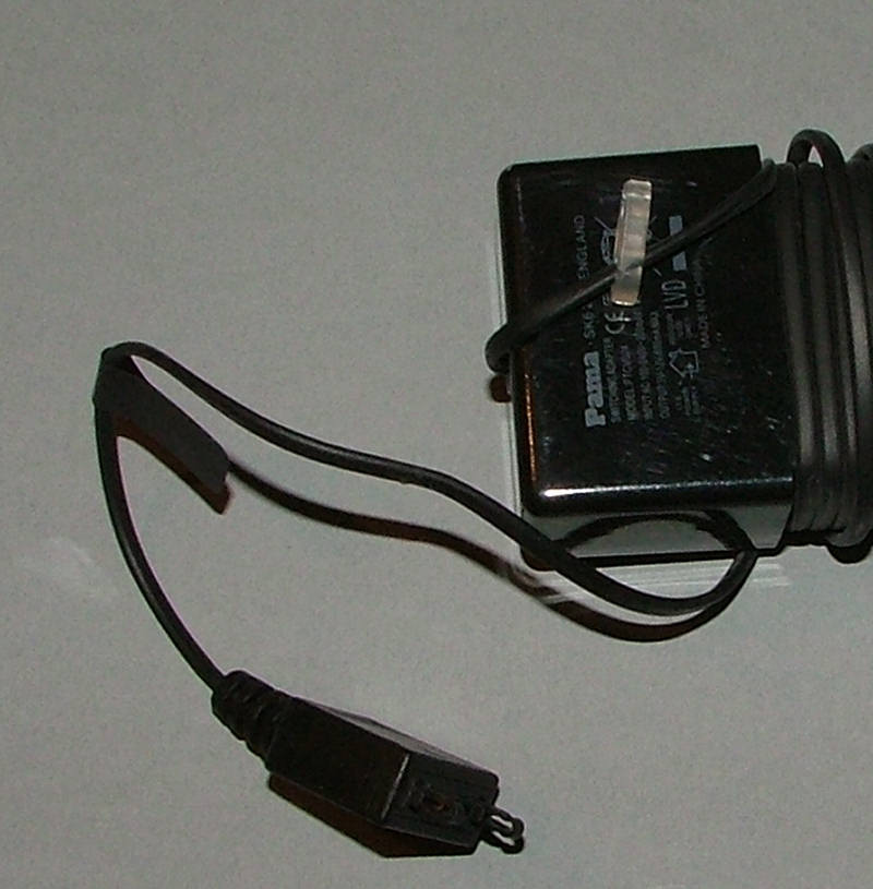
First remove the original connector:
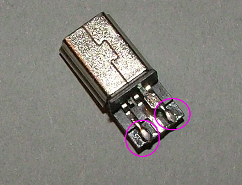
Tin the 2 outer terminals of the USB plug:
Strip the outer insulation of the PSU cable back about 20mm then strip and tin the wire ends. Solder them as shown to the USB plug.
If you have a power supply with black and green wires use this photo:
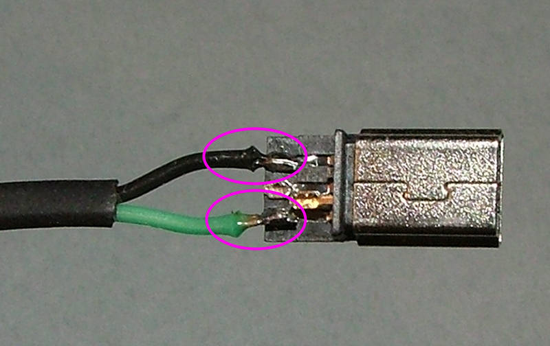
If you have a power supply with red and green wires use this photo:
Finally use the 2 black plastic housing pieces to finish the plug assembly.
UK USB power supply
Return to “Assembly Instructions for the IN-14 5-tube clock”
Jump to
- Timelord Kits
- ↳ Plasma button of Doooom
- ↳ Nixie thermometer V1
- ↳ Assembly instructions for the Thinkgeek nixie thermometer
- ↳ Nixie chessboards
- ↳ Nixie Chessboard V1
- ↳ Assembly instructions
- ↳ Nixie Chessboard V1.5
- ↳ Assembly instructions
- ↳ Nixie Chessboard V1.6
- ↳ Assembly Instructions
- ↳ Nixie OXO board V1
- ↳ OXO board assembly instructions
- ↳ 5-tube nixie clocks
- ↳ IN-14 V1 5-tube nixie clock
- ↳ Assembly Instructions for the IN-14 5-tube clock
- ↳ Mad science Nixie clock - TBA
- ↳ The Coppertop IN-8-2 kit
- ↳ Assembly instructions for the Coppertop clock kit
- ↳ The Cylinder IN-12 V3 Clock
- ↳ Assembly instructions for the Cylinder V3 clock kit
- ↳ Time Flies
- ↳ Setup and operating help
- ↳ Assembly instructions - kit version
- ↳ 1 - GPS mouse
- ↳ 2 - Power controller
- ↳ 3 - Levitation base
- ↳ 4 - Clock modules
- ↳ Beacon
- ↳ Relay 5-tube
- General discussion
- ↳ General discussion
- ↳ Gallery