This is posted elsewhere but I've copied it here as well for ease of use.
NOTE these haven't been used for many years now and this is just left here for reference.
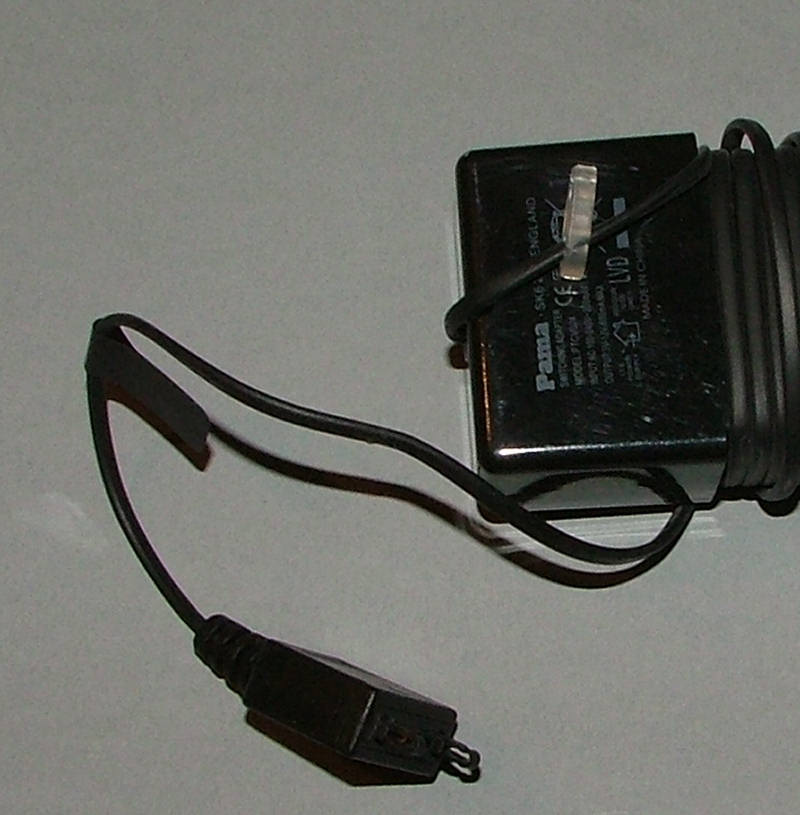
First remove the original connector:
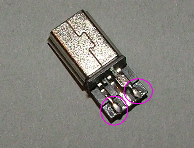
Tin the 2 outer terminals of the USB plug:
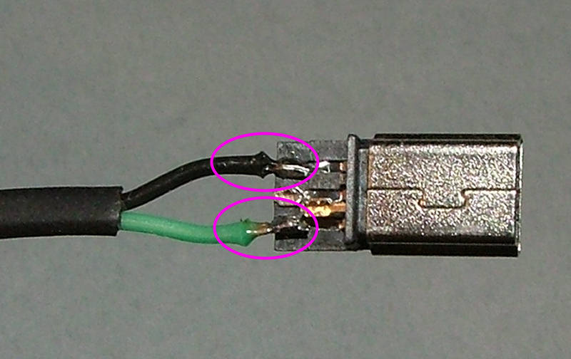
Strip the outer insulation of the PSU cable back about 20mm then strip and tin the wire ends. Solder them as shown to the USB plug.
If you have a power supply with black and green wires use this photo:
If you have a power supply with red and green wires use this photo:
Finally use the 2 black plastic housing pieces to finish the plug assembly.
UK USB power supply
Return to “Assembly instructions for the Thinkgeek nixie thermometer”
Jump to
- Timelord Kits
- ↳ Plasma button of Doooom
- ↳ Nixie thermometer V1
- ↳ Assembly instructions for the Thinkgeek nixie thermometer
- ↳ Nixie chessboards
- ↳ Nixie Chessboard V1
- ↳ Assembly instructions
- ↳ Nixie Chessboard V1.5
- ↳ Assembly instructions
- ↳ Nixie Chessboard V1.6
- ↳ Assembly Instructions
- ↳ Nixie OXO board V1
- ↳ OXO board assembly instructions
- ↳ 5-tube nixie clocks
- ↳ IN-14 V1 5-tube nixie clock
- ↳ Assembly Instructions for the IN-14 5-tube clock
- ↳ Mad science Nixie clock - TBA
- ↳ The Coppertop IN-8-2 kit
- ↳ Assembly instructions for the Coppertop clock kit
- ↳ The Cylinder IN-12 V3 Clock
- ↳ Assembly instructions for the Cylinder V3 clock kit
- ↳ Time Flies
- ↳ Setup and operating help
- ↳ Assembly instructions - kit version
- ↳ 1 - GPS mouse
- ↳ 2 - Power controller
- ↳ 3 - Levitation base
- ↳ 4 - Clock modules
- ↳ Beacon
- ↳ Relay 5-tube
- General discussion
- ↳ General discussion
- ↳ Gallery