3 - Coil Assembly

Tony
Site Admin
Posts: 948
Joined: Tue Jul 24, 2012 8:05 pm

3 - Coil Assembly

Post by Tony »

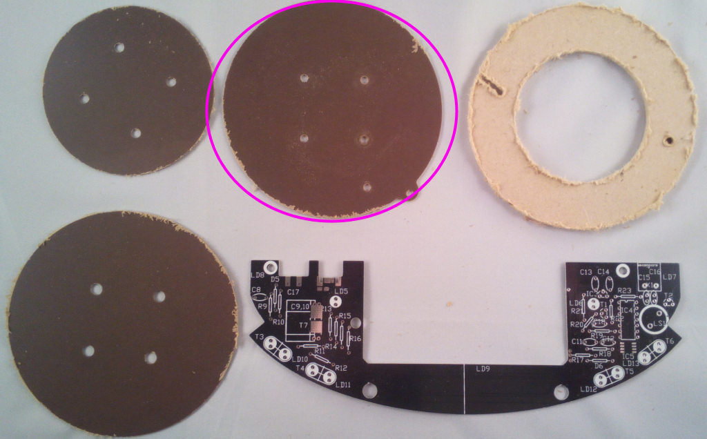
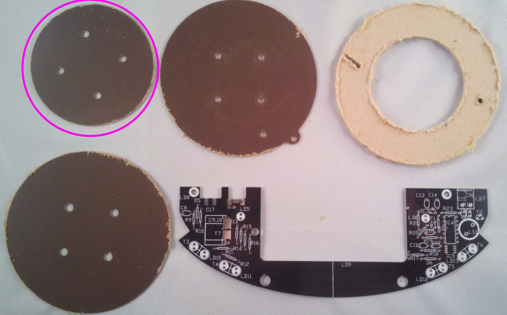
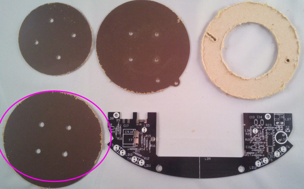
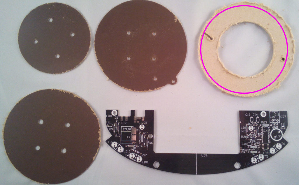
To wind the base coil you'll need the circular coil former pieces from bag4 and the bundle of wire from bag1.
You'll need to sand the former pieces first but as they're not seen don't worry about scratching them.

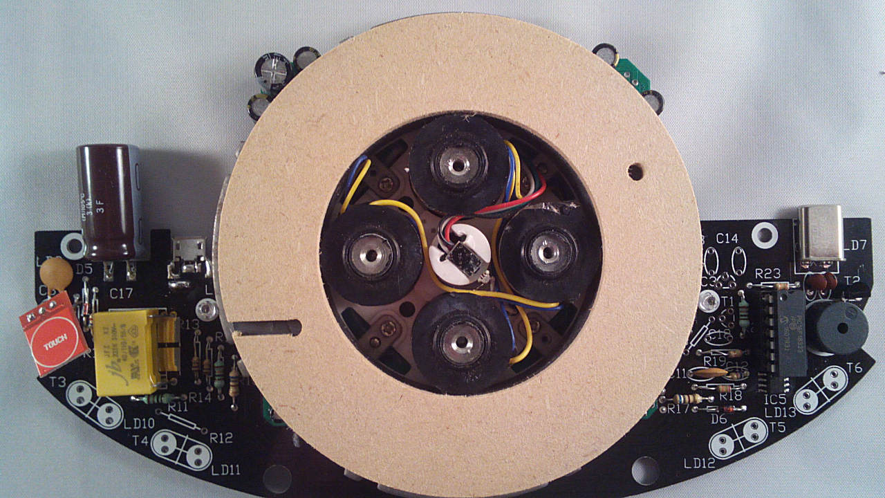
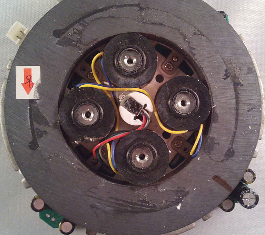
Start by removing the small magnets from the electrmagnets, if fitted:

Image

Leaving the threaded holes clear to fit the coil:
Image

NOTE I have been helpfully sent one box of bases which didn't have these drilled but look the same until the magnets are removed. If you've been sent one of these please do the following.

The coil former will need to be temporarily assembled on its own using 4x M3 bolts and nuts from the base fixings pack to fix the 3 paxolin pieces together, the coil can then be wound and sealed with superglue or similar. Once set remove the temporary bolts and glue the MDF spacer and coil to the magnet base.
Last edited by Tony on Sat Dec 23, 2017 9:31 pm, edited 1 time in total.
Tony
Site Admin
Posts: 948
Joined: Tue Jul 24, 2012 8:05 pm

Re: 3 - Coil Assembly

Post by Tony »

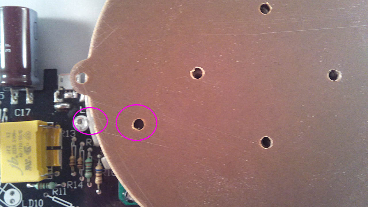
Starting with the MDF spacer, asseble the coil former stack. Make sure the slot is facing as shown in the picture:

Image

Image
Tony
Site Admin
Posts: 948
Joined: Tue Jul 24, 2012 8:05 pm

Re: 3 - Coil Assembly

Post by Tony »

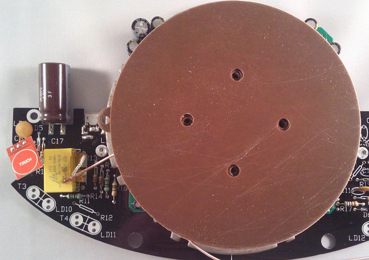
Next is the bottom laminate disc, make sure the hole lines up with the slot in the MDF spacer:

Image

Image
Tony
Site Admin
Posts: 948
Joined: Tue Jul 24, 2012 8:05 pm

Re: 3 - Coil Assembly

Post by Tony »

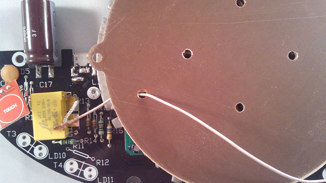
Feed the wire through that hole and the slot, leaving just enough to reach the yellow capacitor pads:

Image
Tony
Site Admin
Posts: 948
Joined: Tue Jul 24, 2012 8:05 pm

Re: 3 - Coil Assembly

Post by Tony »

Next the laminate spacer:

Image

Image
Tony
Site Admin
Posts: 948
Joined: Tue Jul 24, 2012 8:05 pm

Re: 3 - Coil Assembly

Post by Tony »

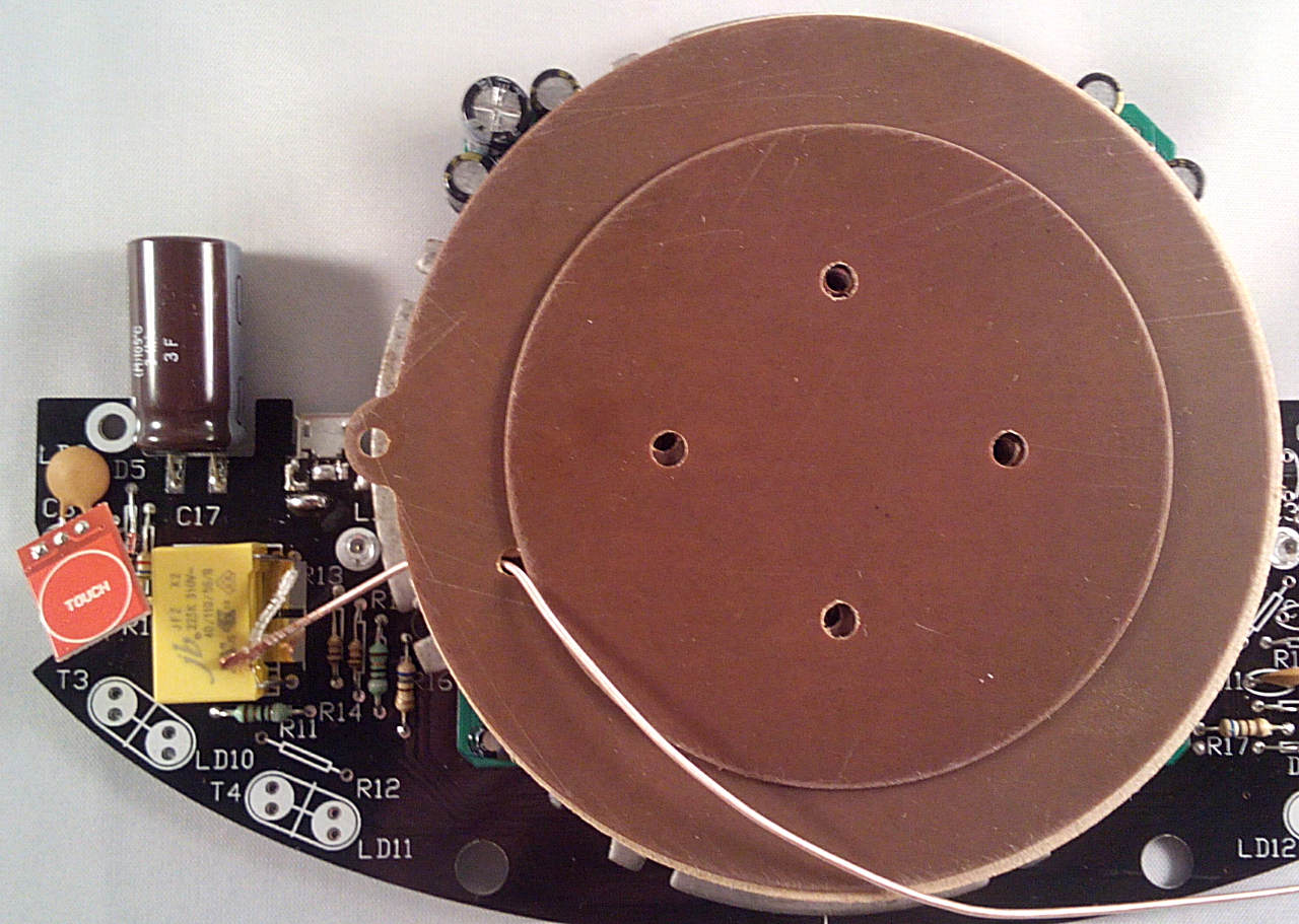
Then the laminate top disc:

Image

Image
Tony
Site Admin
Posts: 948
Joined: Tue Jul 24, 2012 8:05 pm

Re: 3 - Coil Assembly

Post by Tony »

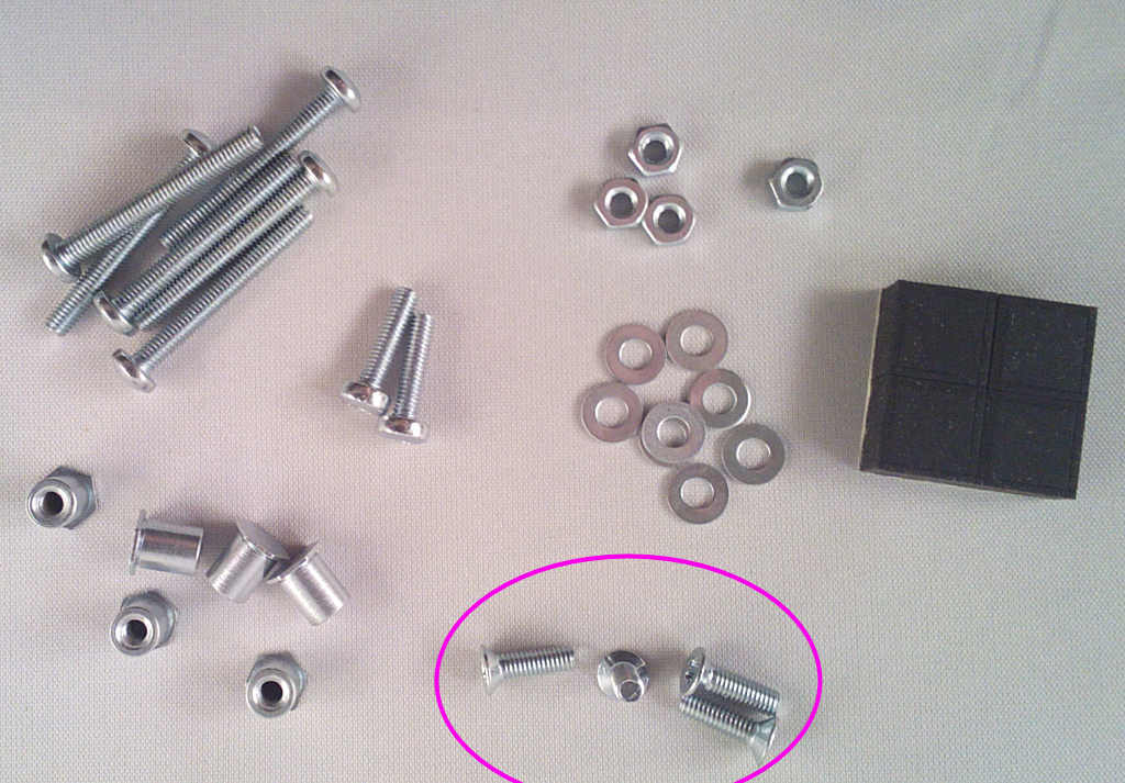
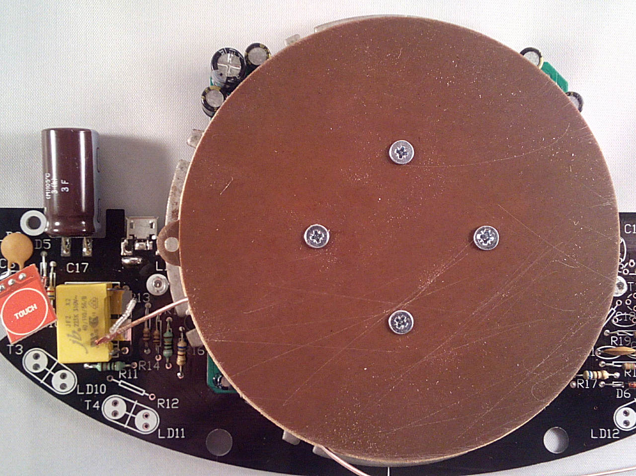
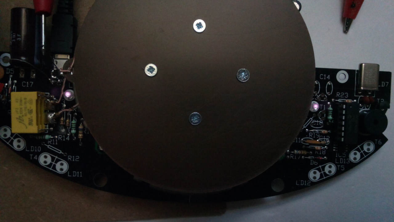
Bolt them down using the 4x M12 countersunk bolts in Bag4 - make sure all the pieces are centred:

Image

Image
Tony
Site Admin
Posts: 948
Joined: Tue Jul 24, 2012 8:05 pm

Re: 3 - Coil Assembly

Post by Tony »

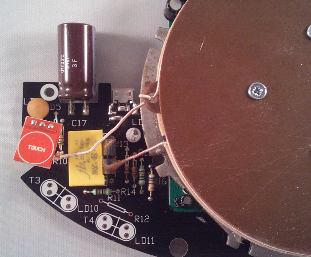
Now carefully wind 13 turns of wire onto the former. There's not much space so they'll need to be fairly tight and the last turn will be just over the edge of the discs.

Image

Cut the wire leaving just enough to reach the capacitor pads and feed it through the hole in the bottom laminate disc tab.
Tony
Site Admin
Posts: 948
Joined: Tue Jul 24, 2012 8:05 pm

Re: 3 - Coil Assembly

Post by Tony »

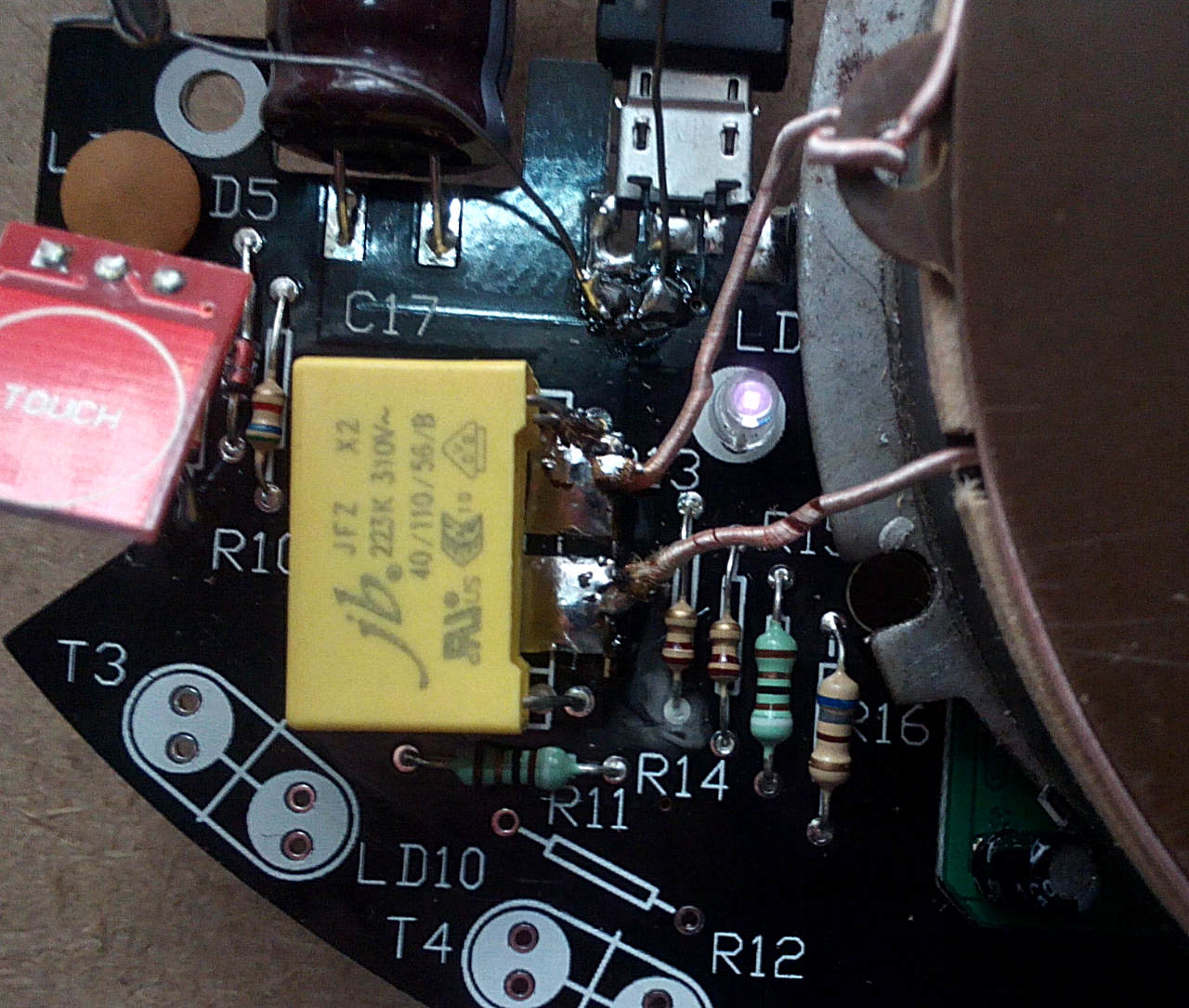
Tin the wire ends and solder them to the 2 square pads between the yellow capacitor leads:

Image

Reconnect the multimeter and connect the USB power cable. Switch on and check the current drawn now - it should be 220-240mA. Make a loop of solder and move it close to the base coil - the current should increase considerably.
Using a camera phone, view the infra red LEDs and check they flash once a second:

Image

If everything is working as expected, unplug and remove the meter leads. Unsolder the test point wires and bridge the 2 pads with solder. You should now have a working base unit to allow you to build and test the floating clock section - I'd recommend doing that before assembling the case just to confirm everything is working.
Zedsquared
Posts: 11
Joined: Tue Nov 07, 2017 9:56 pm

Re: 3 - Coil Assembly

Post by Zedsquared »

[quote="Tony"]Bolt them down using the 4x M12 countersunk bolts in Bag3 - make sure all the pieces are centred:

That'll be bag 4 ... or it was in my kit :)
Locked