Board PCB - Red version

Assembly instructions for our limited edition OXO board
Tony
Site Admin
Posts: 948
Joined: Tue Jul 24, 2012 8:05 pm

Board PCB - Red version

Post by Tony »

From mid-2018 the PCB is RED with through-hole parts, much easier to assemble than the earlier SMD board.
Both sets of instructions will be left here as there will still be a few of the original kits left.

Unpack the component bag and sort them out into separate piles. You should have:

9x 2n7000 transistors (3 legged black plastic) These must be fitted the right way round.
9x 1n ceramic capacitors (Yellow resin)
1x 4v7 zener diode (glass bead with 2 leads) This must be fitted the right way round.
6x 10n capacitors (brown ceramic)
7x 22u capacitors (black metal cylinder)
1x 1k or 1k2 resistor (Brown Black Red or Brown Red Red)
1x 24k resistor (Orange Yellow Orange)
1x Polyfuse marked F030
2x 9 way D socket, for tube pins
12x M3x16 bolts, M3 washers and M3 dome nuts for case assembly.
4x rubber feet
5g solder
1x 3.1mm socket

Start by fitting R1, 1K:
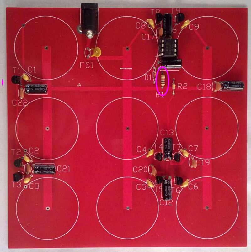
Image
Tony
Site Admin
Posts: 948
Joined: Tue Jul 24, 2012 8:05 pm

Re: Board PCB - Red version

Post by Tony »

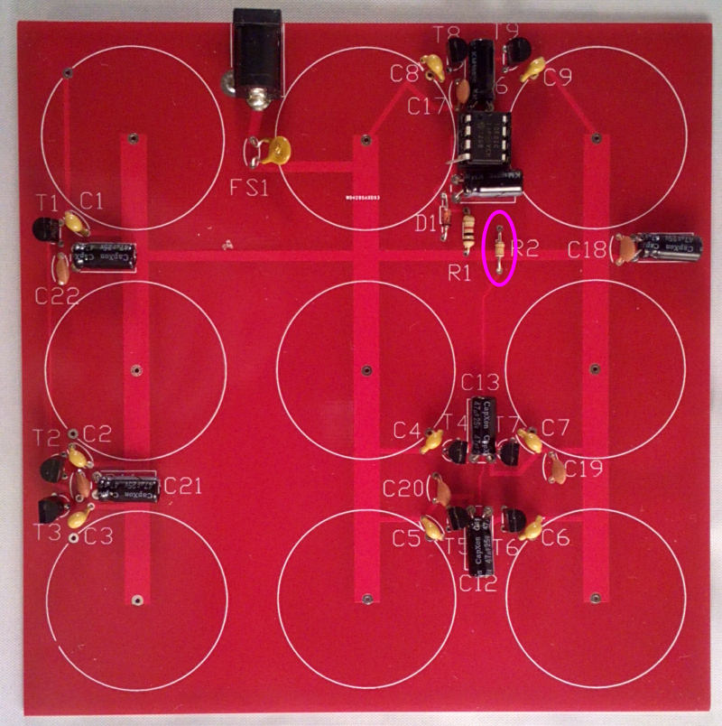
Next fit R2, 24k:

Image
Tony
Site Admin
Posts: 948
Joined: Tue Jul 24, 2012 8:05 pm

Re: Board PCB - Red version

Post by Tony »

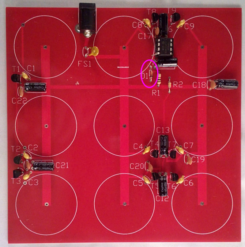
Then D1, the 4v7 zener. Note the band faces DOWN away from IC1:

Image
Tony
Site Admin
Posts: 948
Joined: Tue Jul 24, 2012 8:05 pm

Re: Board PCB - Red version

Post by Tony »

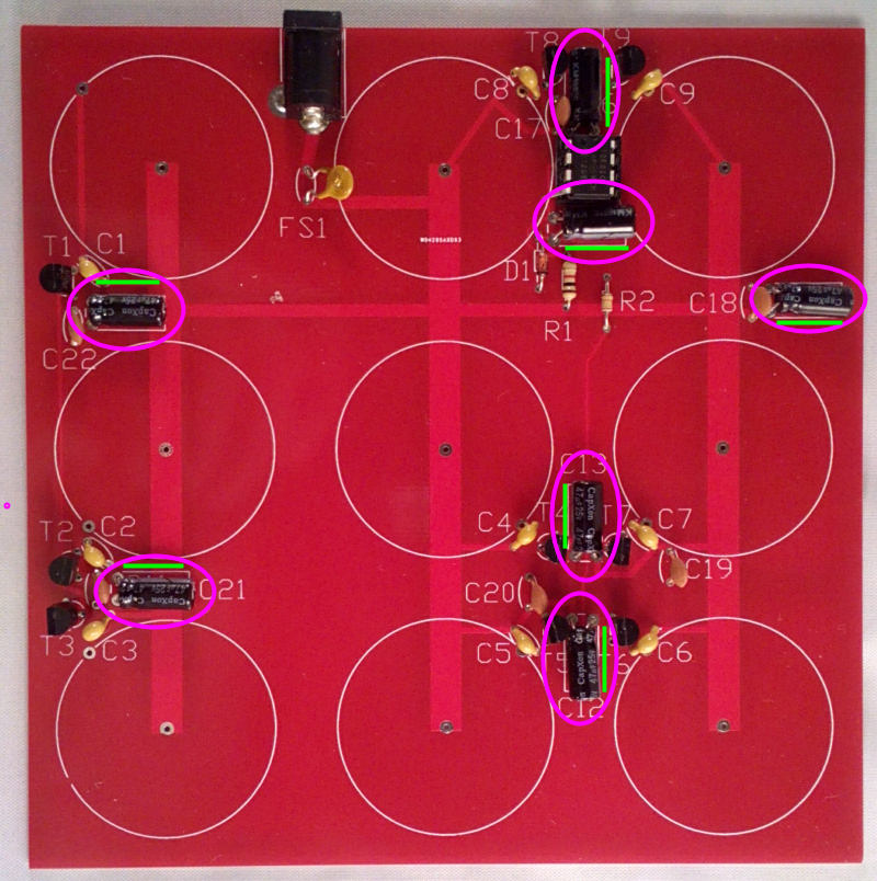
Next the 6 electrolytic capacitors., leave out C15. Note that these are polarised and the negative band on the case must face the same way as the green lines in the picture.

Image
Tony
Site Admin
Posts: 948
Joined: Tue Jul 24, 2012 8:05 pm

Re: Board PCB - Red version

Post by Tony »

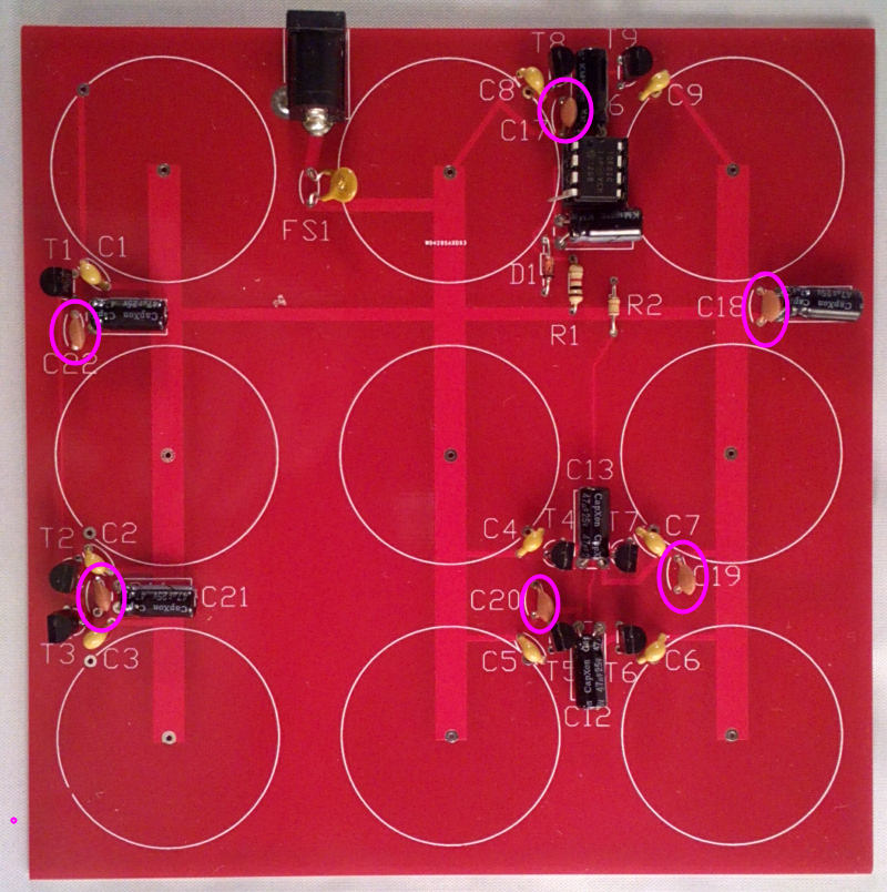
Then the 6x 10n (103) or 33n (333) brown ceramic disc capacitors:

Image
Tony
Site Admin
Posts: 948
Joined: Tue Jul 24, 2012 8:05 pm

Re: Board PCB - Red version

Post by Tony »

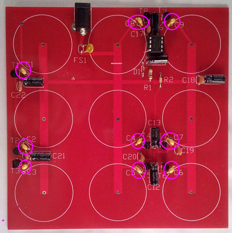
Last capacitors and almost time for the first test. Fit the 9x 1n (102) Mylar or ceramics:

Image
Tony
Site Admin
Posts: 948
Joined: Tue Jul 24, 2012 8:05 pm

Re: Board PCB - Red version

Post by Tony »

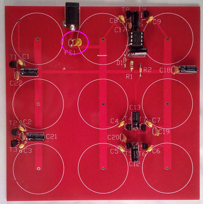
Solder the power socket in place, followed bt the polyfuse FS1 (F030):

Image
Tony
Site Admin
Posts: 948
Joined: Tue Jul 24, 2012 8:05 pm

Re: Board PCB - Red version

Post by Tony »

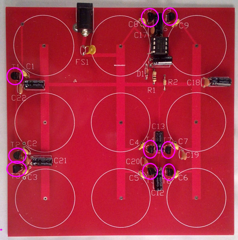
Now connect a multimeter on a 0-20 volts range (or as close as your meter will allow) across D1. Connect the power supply to SK1 and switch on. You should see just under 5V there. If it's 12V check you used the correct diode, if it's under 1V check it's the right way round. Check FS1 isn't getting warm, if everything is OK we can move on to fitting the transistors - 9x 2n7000. Make sure they're fitted the right way round as marked on the PCB and in the photo:

Image
Tony
Site Admin
Posts: 948
Joined: Tue Jul 24, 2012 8:05 pm

Re: Board PCB - Red version

Post by Tony »

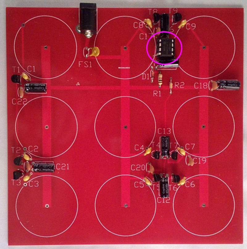
Now fit the 8-pin IC socket and then IC1. Bend pin 4 out to one side and make sure it's fitted with the notch marking pin1 facing up to the top edge of the board.

Image
Tony
Site Admin
Posts: 948
Joined: Tue Jul 24, 2012 8:05 pm

Re: Board PCB - Red version

Post by Tony »

Connect your multimeter negative probe to the top end of D1 (closest to IC1) and the positive probe to the lower end of FS1. Switch on again, it should read about 11.5V. If it's lower than 11V switch off and check for shorts, if not let ir run for a few seconds. You should start to feel the printed coils getting warm but not hot. If all 9 are about the same, it's complete and ready to use. If one remains cold, check the soldering around that transistor.
Post Reply