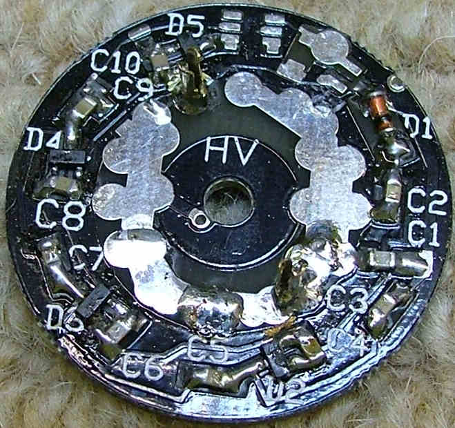
Am I correct that the IN-7 is this item: http://www.tube-tester.com/sites/nixie/ ... 7/in-7.htm?Tony wrote:Tin the cut end of 2 pins then put a blob of solder on the pads shown here:
Looking from under the nixie, pins are counted clockwise from the gap
with the first to the right of it being pin 1.
Make four of these for use with 4x IN-7A/IN-7 for the '+'. pin 2 is connected to the pad marked 'HV' and pin 4 to the pad
next to D4.
Piece base PCB
Re: Piece base PCB - SMD version
Re: Piece base PCB
Am I correct that the IN-4 is this item: http://www.tube-tester.com/sites/nixie/ ... -4-sh2.htm?Tony wrote:If you have the later kit with IN-4 nixies use this picture - note the right-hand pin is slightly to the left of the pad on the PCB to allow the correct pin spacing.
XXXSnipXXX
The IN-4 is used for the '0' and has pin 10 connected to HV and pin 8 to
ground, which is the pad to the right. Again you'll need five of these.
Re: Piece base PCB
1. This looks somewhat different to my completed PCB. e.g. D5 is not installed. I presume the images are of a different version?Tony wrote:XXXsnipXXX
2. I assume the NIXIE is powered by some kind of HF transformer. What is the approximate signal that should be received by the PCB from the transformer coil on it? Is this a sine wave at what frequency? What is the peak-to-peak voltage?
3. At the terminals for powering the NIXIE what is the voltage profile that should appear there? I note the strike voltage is about 170V from the urls I found. Can you please confirm the peak-to-peak voltage & waveform.
Thanks!
Re: Piece base PCB
D5 isn't used as the final design didn't need that many multiplier stages. It's an air cored transformer similar in operation to a flyback transformer.
The exact voltage will depend on the spacing but should be around 40-50V at D1. By the time it reaches the nixie you will have 200-250V, this will drop once the tube ignites to the operating voltage of that cathode.
On a scope it will appear as a group of spikes repeated at regular intervals, I can't remember the exact frequency for that version as it was only used in one batch, the later ones switched back to a 12V supply and a different frequency.
Re: Piece base PCB - SMD version
Yes, those are the tubes. I switched from IN-7bjmmcg wrote:Am I correct that the IN-7 is this item: http://www.tube-tester.com/sites/nixie/ ... 7/in-7.htm?Tony wrote:Tin the cut end of 2 pins then put a blob of solder on the pads shown here:
Looking from under the nixie, pins are counted clockwise from the gap
with the first to the right of it being pin 1.
Make four of these for use with 4x IN-7A/IN-7 for the '+'. pin 2 is connected to the pad marked 'HV' and pin 4 to the pad
next to D4.
Re: Piece base PCB
Thanks for the details!Tony wrote:XXXsnipXXX
On a scope it will appear as a group of spikes repeated at regular intervals, I can't remember the exact frequency for that version as it was only used in one batch, the later ones switched back to a 12V supply and a different frequency.
My PCBs are black.
Can I safely assume that the frequency is less than 200kHz?
Sadly I managed to destroy one of the NIXIE driver PCBs due to my ham-fistedness. (First time ever working with surface-mount as opposed to discreet. The OXO kit was a present from a good friend, Robin, you might recall him.)
Re: Piece base PCB
It's much lower than that. If you need any spares let me know as the piece PCBs are still availabe.
Re: Piece base PCB
I sent an email regarding the components I require. I hope you got it.Tony wrote:It's much lower than that. If you need any spares let me know as the piece PCBs are still availabe.
Re: Piece base PCB
FYI a photo of the waveform "powering" the NIXIE.
- Attachments
-
- The test of the NIXIE PCB.
- nixie pcb test 1.JPG (250.29 KiB) Viewed 22386 times
-
- NIXIE PCB waveform. Note 10x voltage scale.
- nixie pcb waveform 1.JPG (246.28 KiB) Viewed 22386 times
