Board PCBs

Assembly instructions for the V1 chessboard.
Tony
Site Admin
Posts: 948
Joined: Tue Jul 24, 2012 8:05 pm

Board PCBs

Post by Tony »

For this you will need the entire contents of BAG 5 and the 4 base PCBs:

Unpack and sort out the components into seperate piles. You should have:

8x Polyfuses (Discs marked F030)
4x 1K resistors (Brown black red) or 470r (yellow purple brown)
12x 5v1 (or 4v7) zener diodes
80x 10n or 33n ceramic capacitors (Brown)
40x 47 or 33u capacitors (Blue or black)
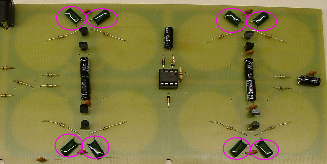
65x 1n ceramic capacitors (Yellow) or Mylar capacitors (Green)
1x 3.1mm socket
D sockets to provide pins for the pieces

Earlier kits also contained 1n4148 diodes, these are omitted from the later kits.
If you received the new single 64-coil PCB you'll also have a strip of about 100x 1R1 resistors.

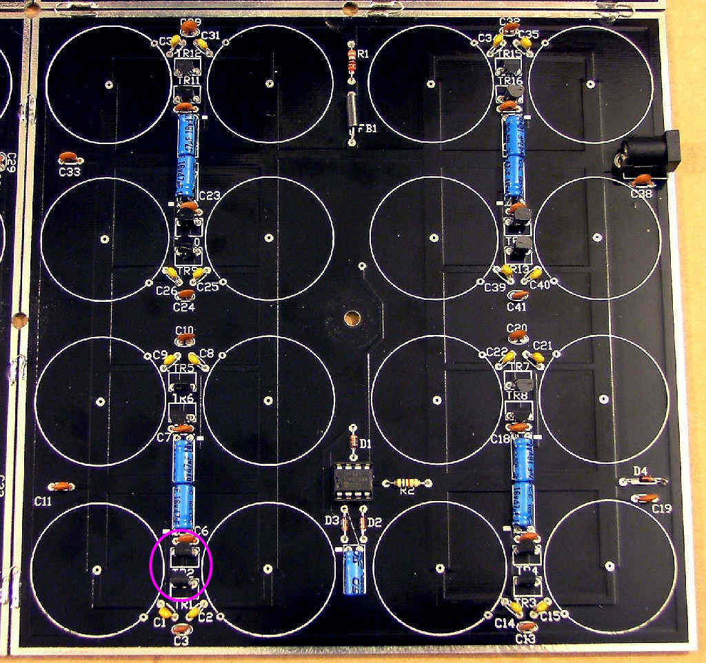
Start with the link:
Image

X64 PCB 1r1 resistors (links):
Image

Image
Tony
Site Admin
Posts: 948
Joined: Tue Jul 24, 2012 8:05 pm

Re: Board PCBs

Post by Tony »

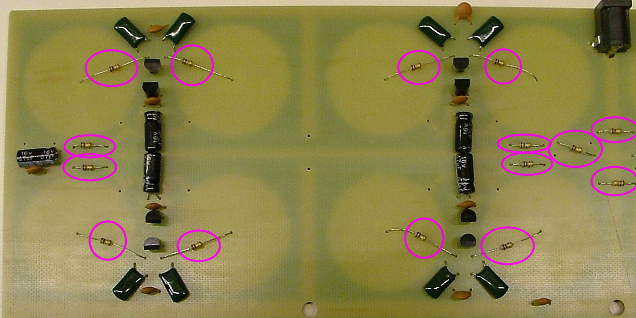
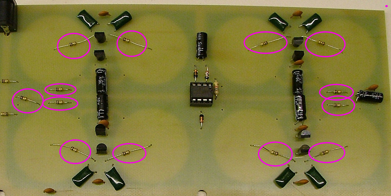
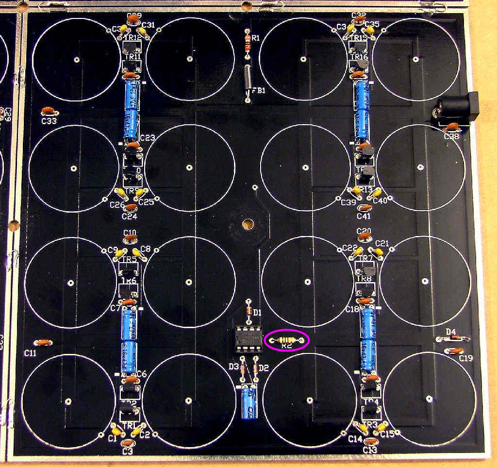
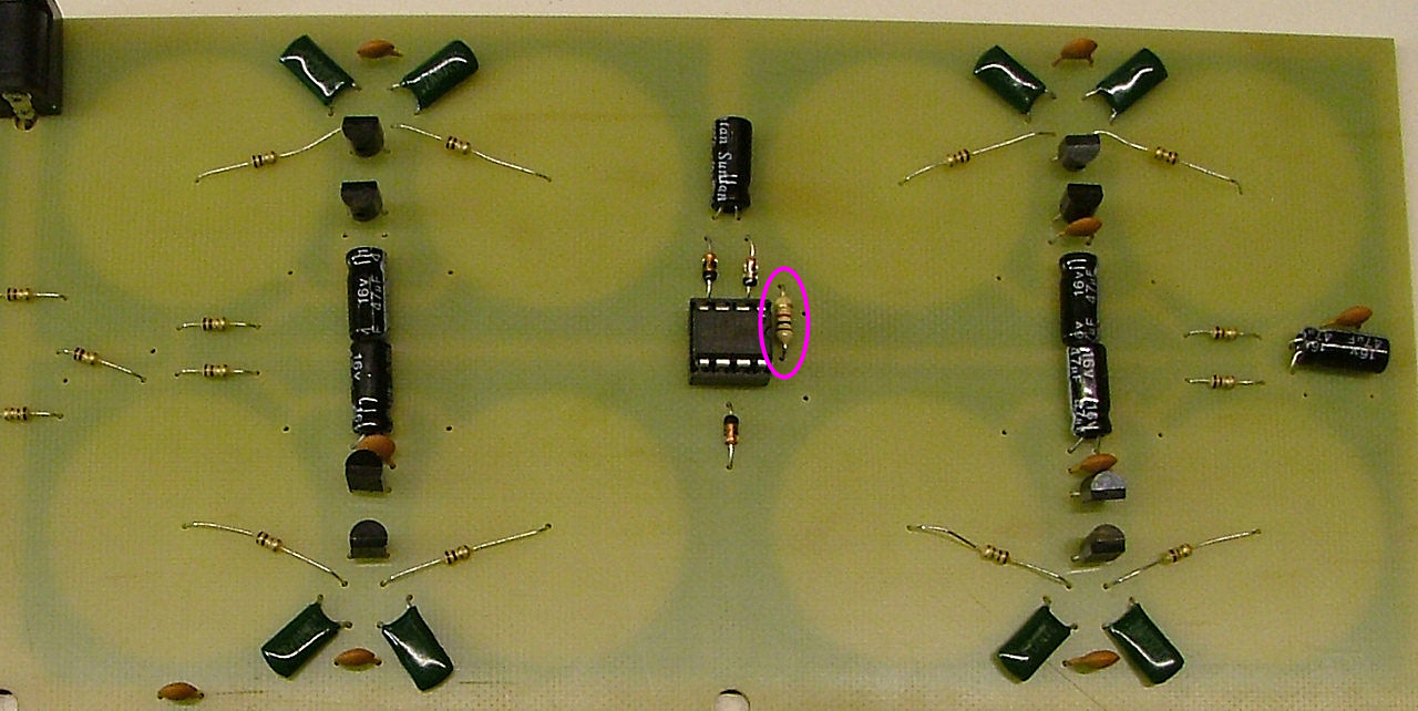
Followed by the 1K or 470r resistor:

Image

Image
Tony
Site Admin
Posts: 948
Joined: Tue Jul 24, 2012 8:05 pm

Re: Board PCBs

Post by Tony »

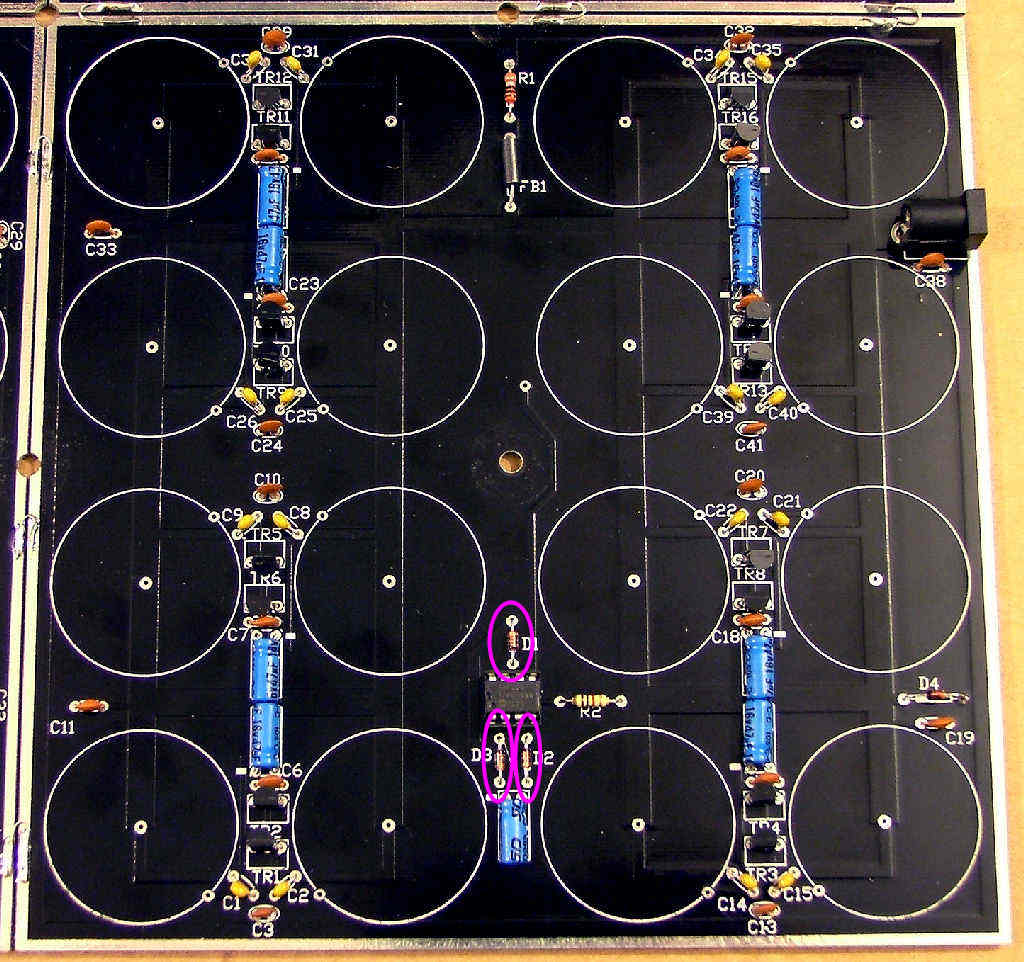
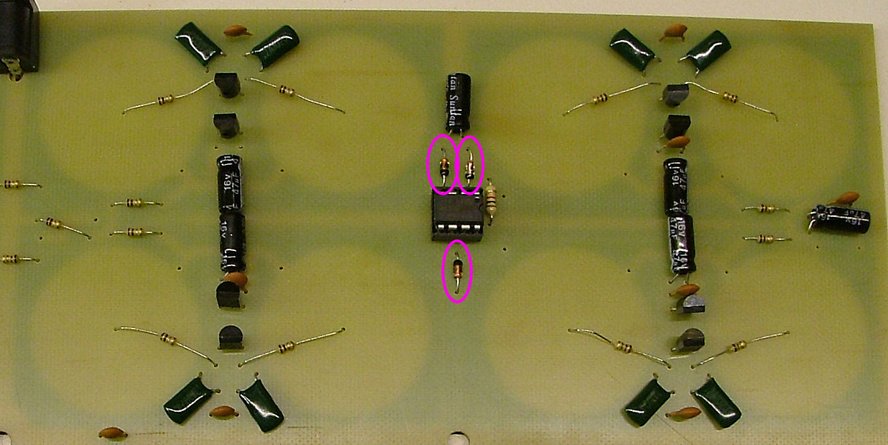
Now the 5V1 zener diodes. Make sure the black band bfaces the right way as marked on the PCB and in the picture:

Image

Image
Tony
Site Admin
Posts: 948
Joined: Tue Jul 24, 2012 8:05 pm

Re: Board PCBs

Post by Tony »

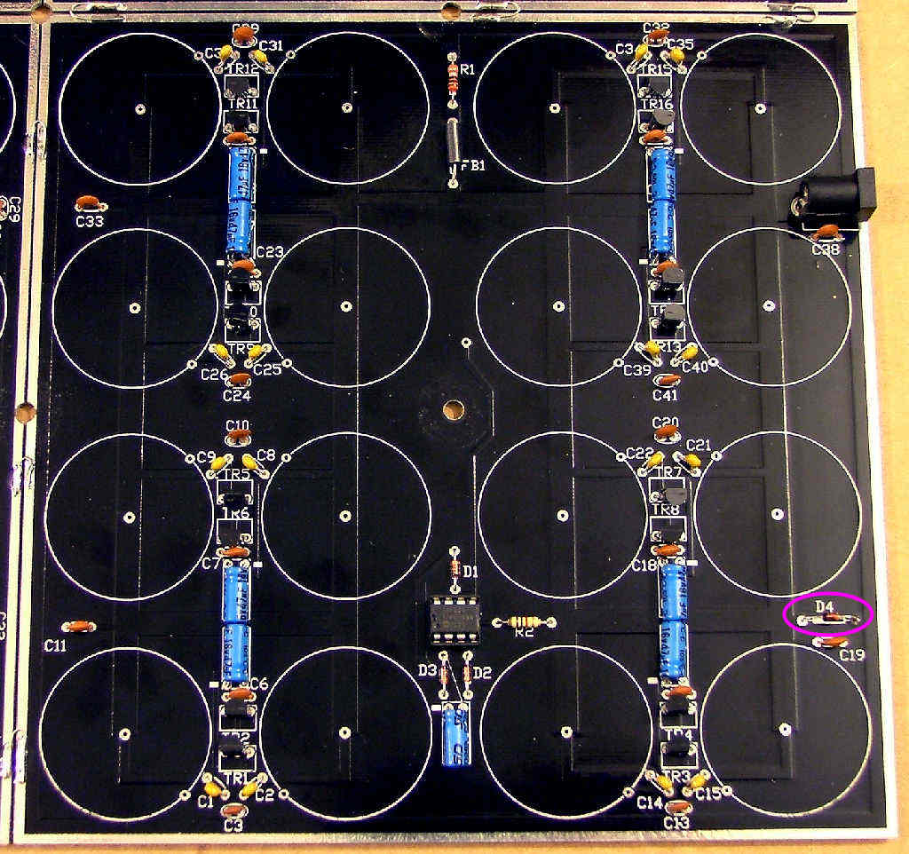
And one 1N4148 diode, again make sure it faces the right way:
(Not used on later kits)

Image
Tony
Site Admin
Posts: 948
Joined: Tue Jul 24, 2012 8:05 pm

Re: Board PCBs

Post by Tony »

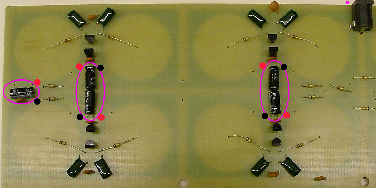
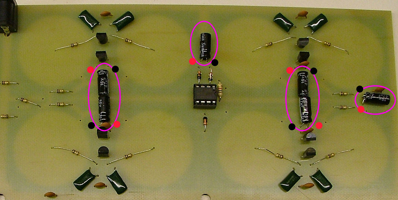
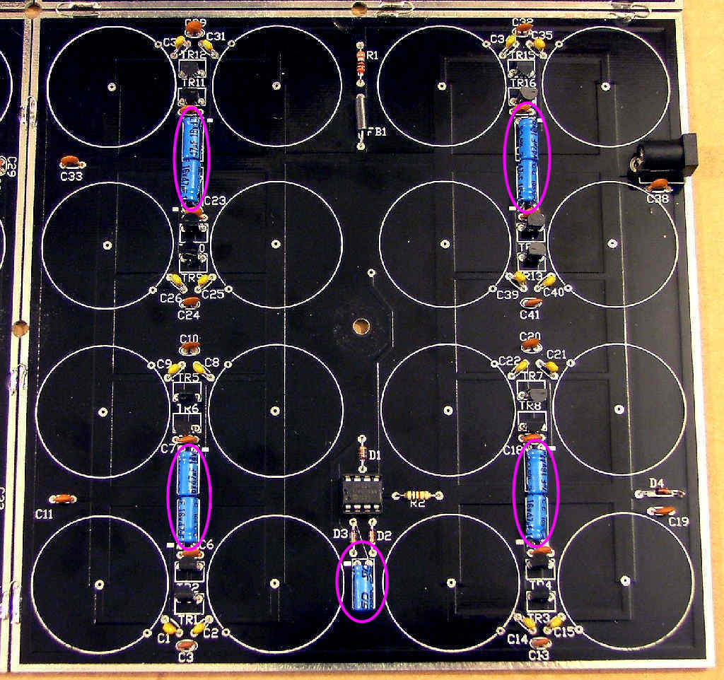
Now the 47u or 33u capacitors. Again these are polarised, the black band on the case faces the '-' mark on the PCB.

Image

Image

Image
Tony
Site Admin
Posts: 948
Joined: Tue Jul 24, 2012 8:05 pm

Re: Board PCBs

Post by Tony »

Temporarily fit the power socket - unless it's the last board:

Image

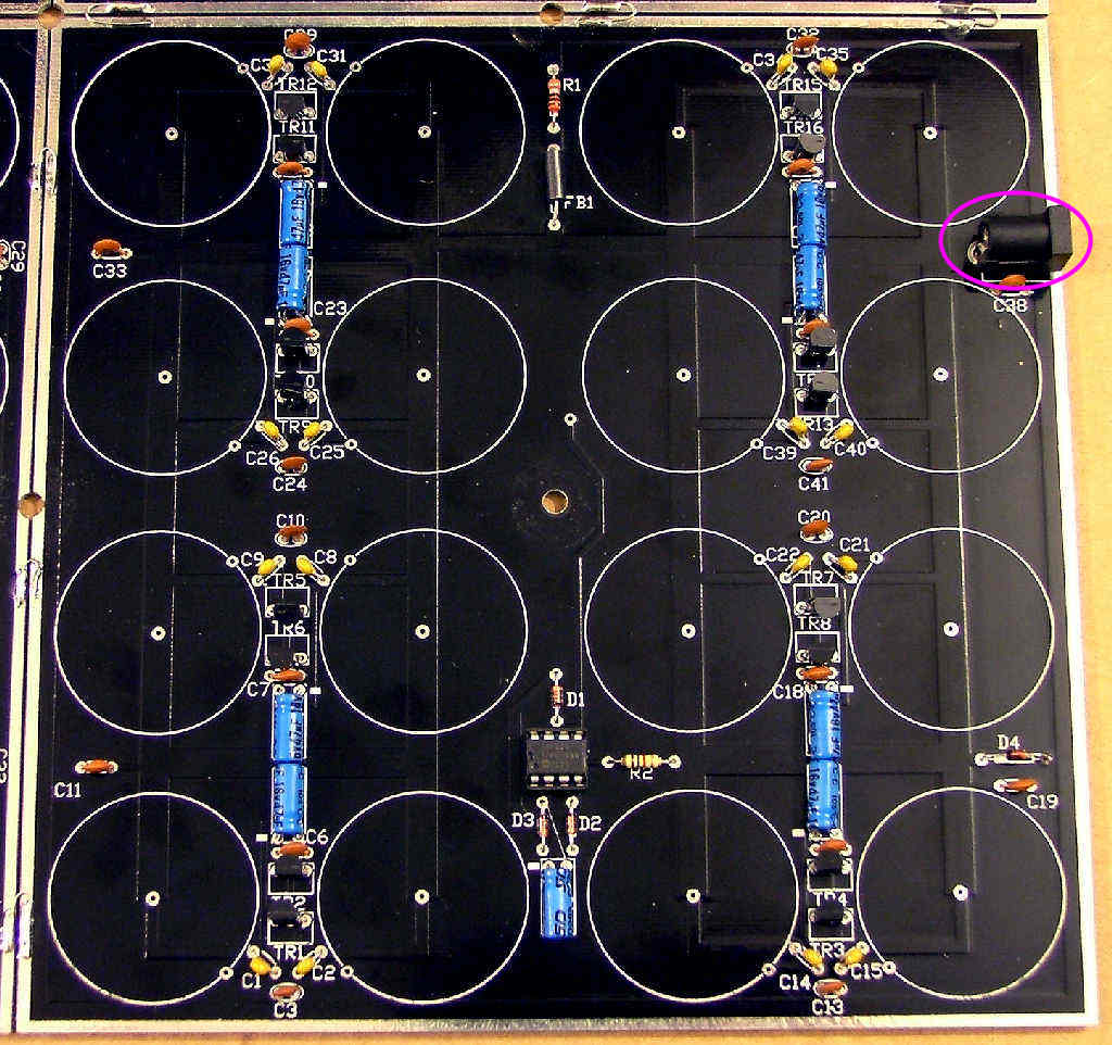
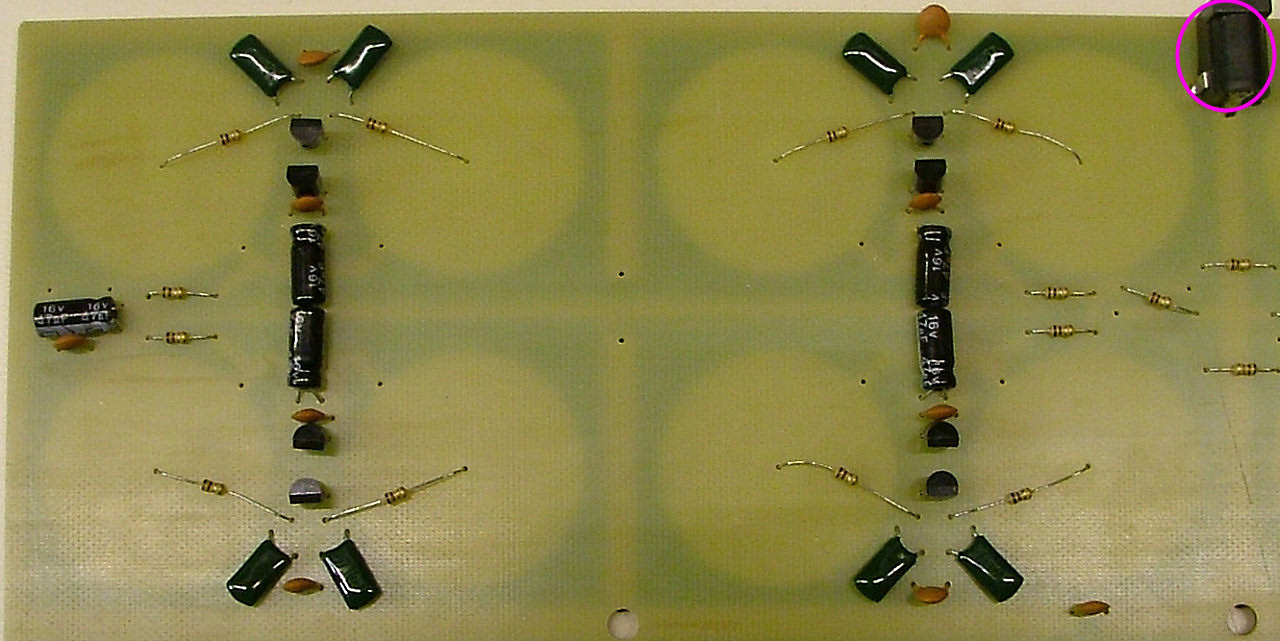
For the x64 board there's only one place for the power socket so fit it at this stage:

Image
Tony
Site Admin
Posts: 948
Joined: Tue Jul 24, 2012 8:05 pm

Re: Board PCBs

Post by Tony »

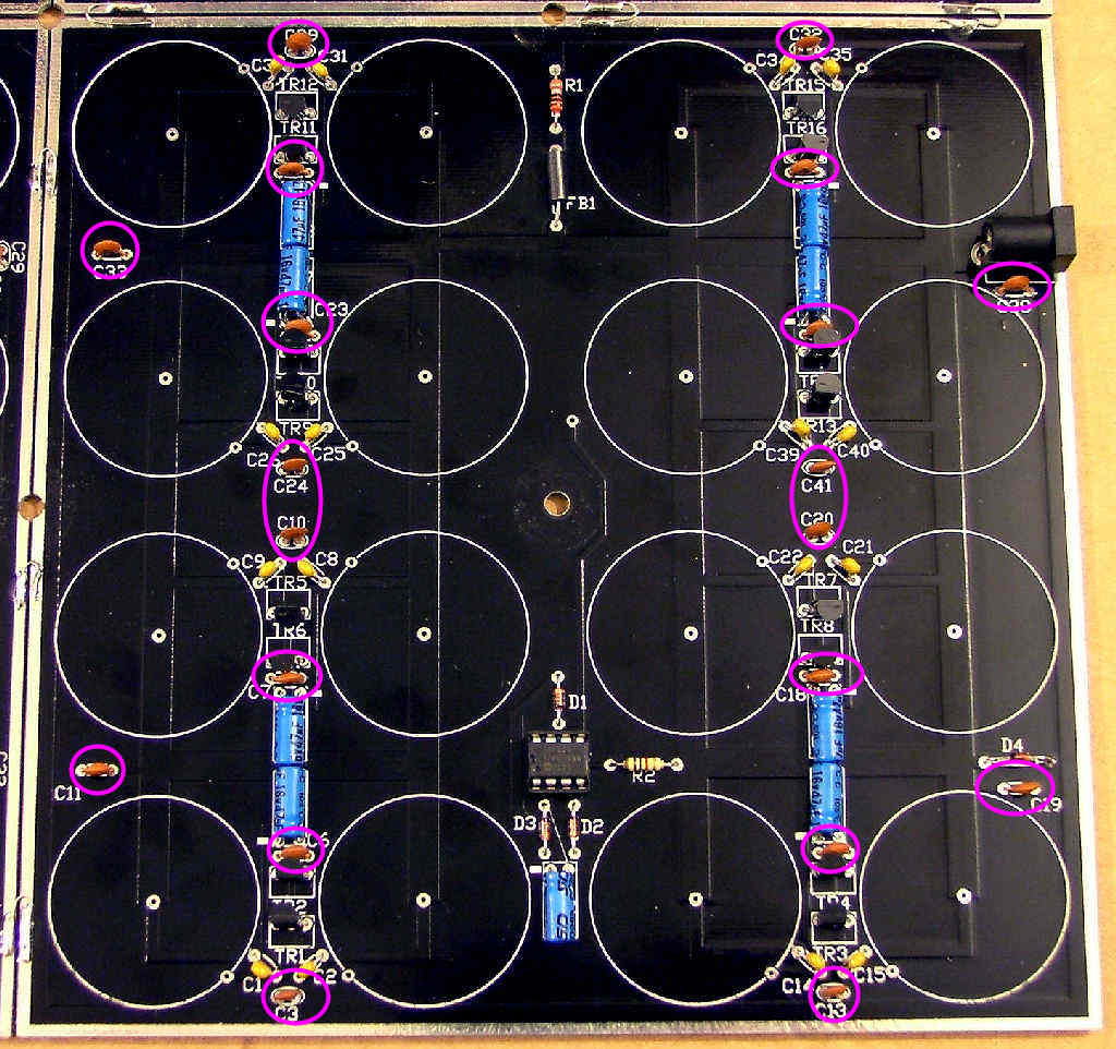
Twenty small 10n or 33n ceramic capacitors:

Image

Image

Image
Tony
Site Admin
Posts: 948
Joined: Tue Jul 24, 2012 8:05 pm

Re: Board PCBs

Post by Tony »

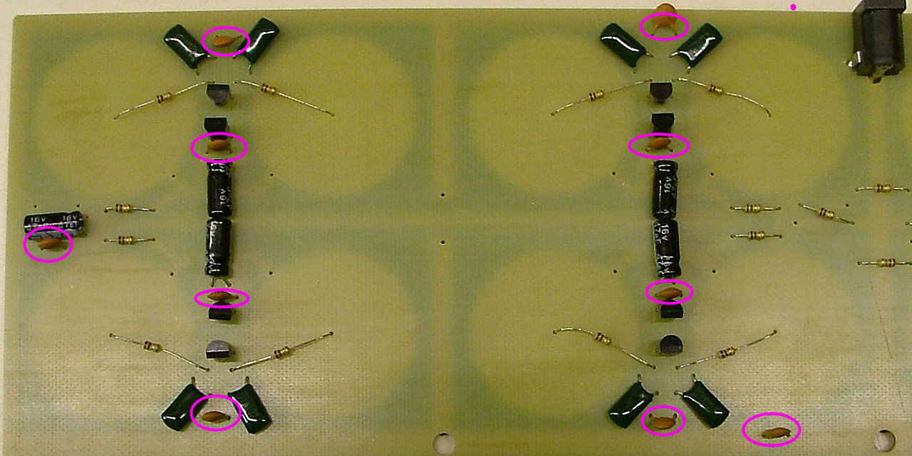
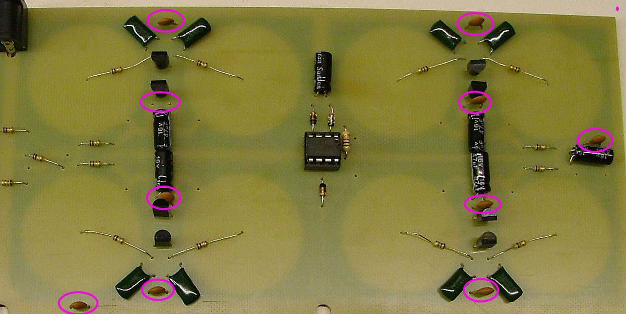
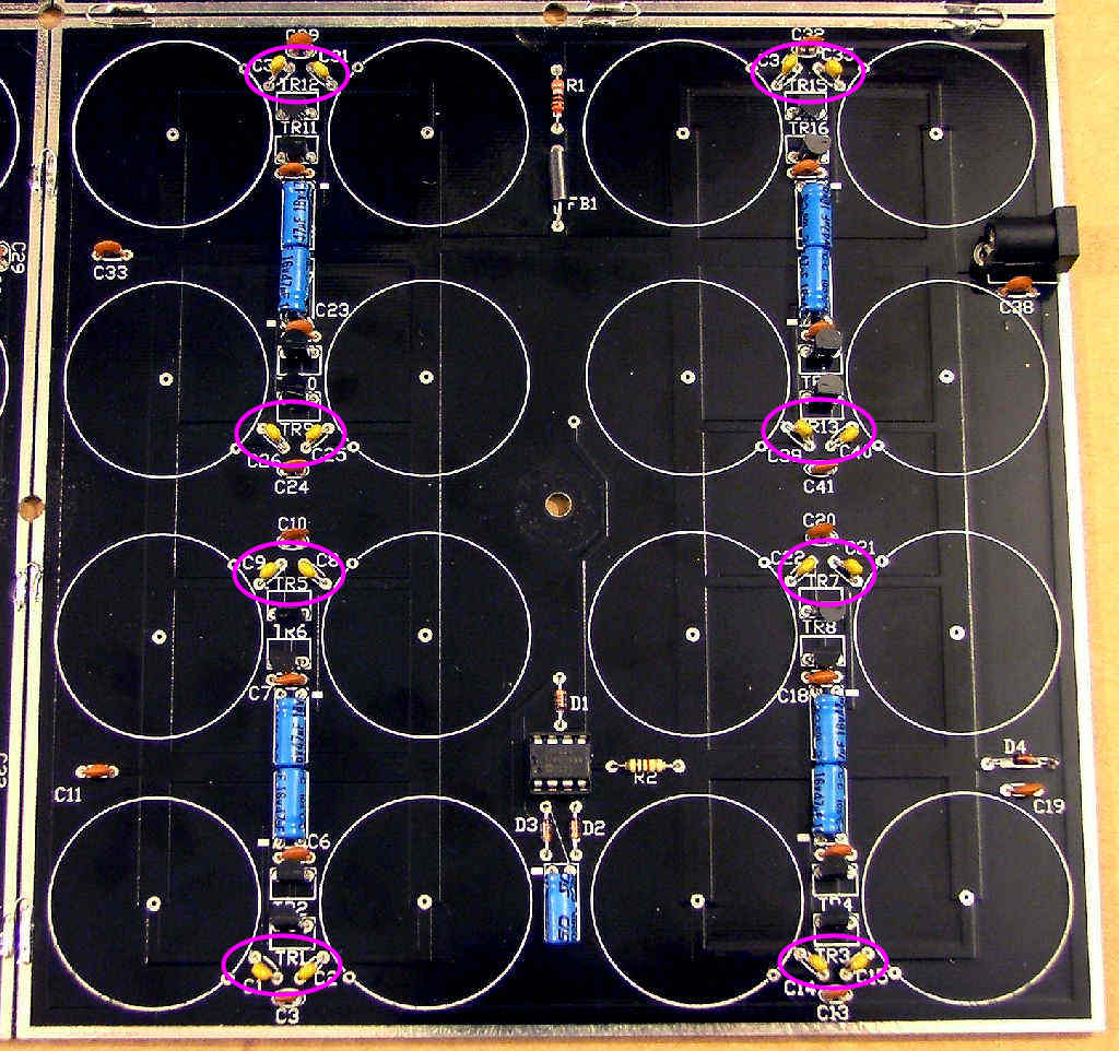
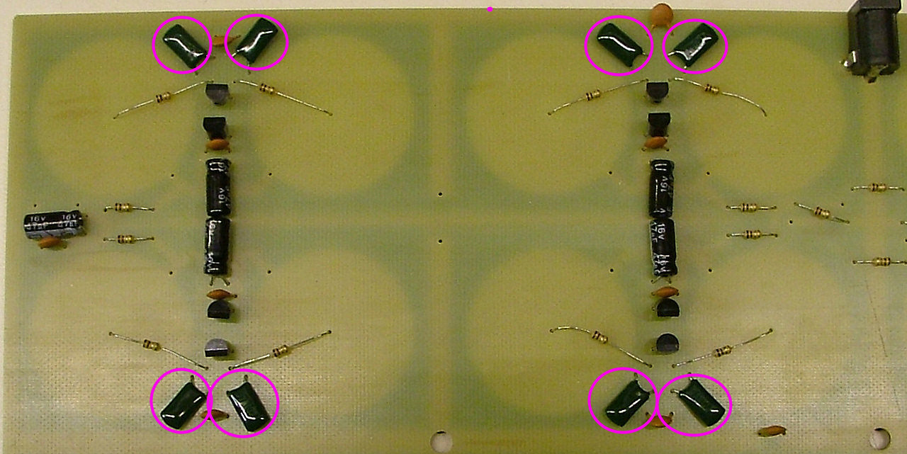
Finally for now the 1n capacitors:

Image

For the x64 board these will be either green resin or yellow plastic:

Image

Image
Tony
Site Admin
Posts: 948
Joined: Tue Jul 24, 2012 8:05 pm

Re: Board PCBs

Post by Tony »

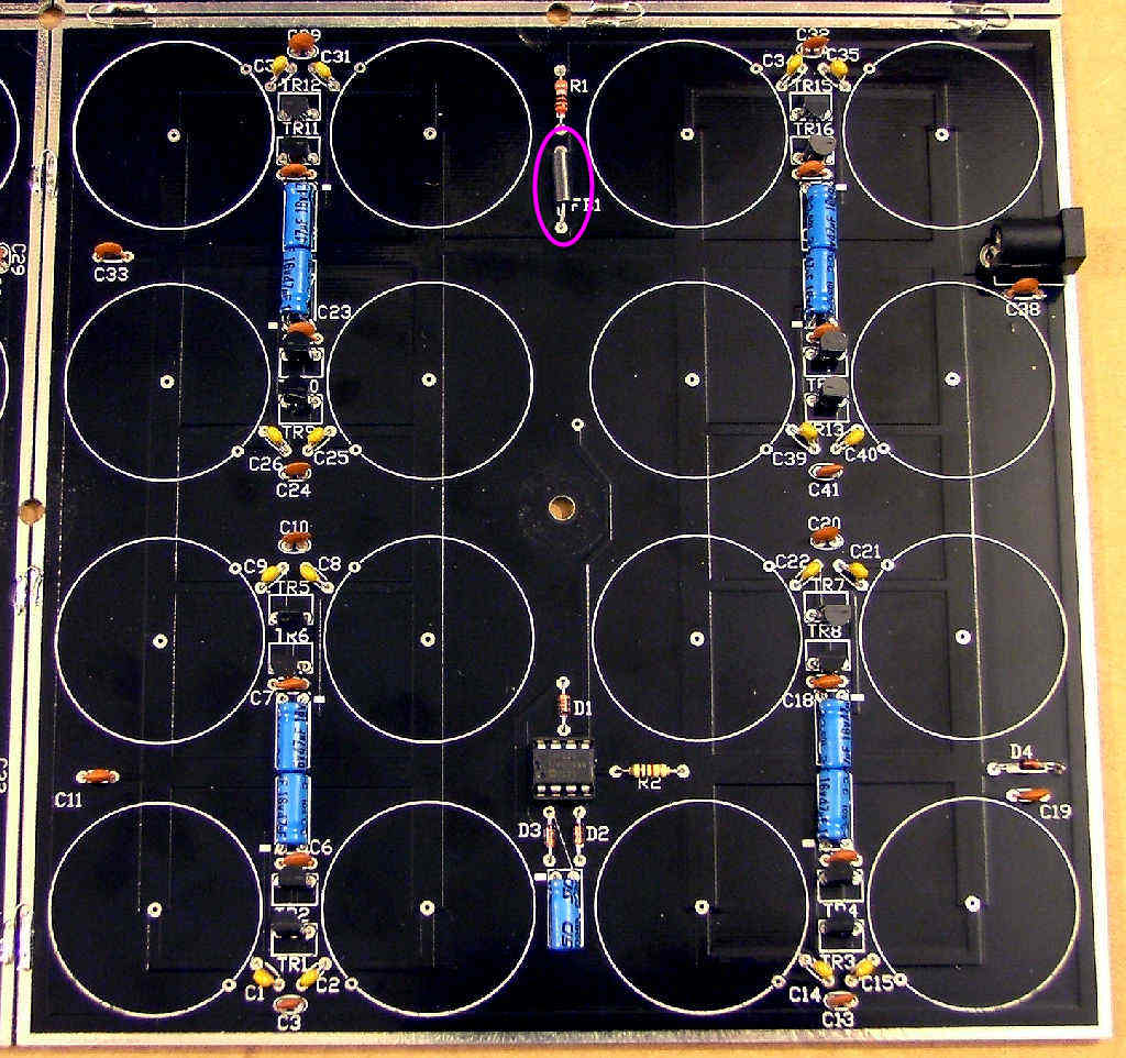
It's now time for the first power test. Connect a multimeter set to read mA across the space for R1. Connect the 12V power supply, the current should be a couple of mA. If more disconnect and check for shorts.

If the reading was OK temporarily fit one of the polyfuses as R1, set your meter to volts and power up again. Check for 5V across D3 (for the x64 board, the top right diode).

Now fit the 8 pin socket and one of the microcontrollers from BAG6, making sure it's the same way round as in the pictures, with the pin 1 mark next to D3.

Power up again and check for 5V again across D3 and about 2V across D1 and D2. If you've got this far it's time to start fitting the transistors. Remove R1 and set your meter to mA again.


For the x64 PCB it's split between R10 and R11, fit R10 and use the above instructions for R11 in place of R1.

Image
Tony
Site Admin
Posts: 948
Joined: Tue Jul 24, 2012 8:05 pm

Re: Board PCBs

Post by Tony »

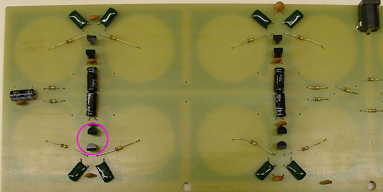
Fit two transistors from BAG6 as shown, the flat edge will always face AWAY from the 47u capacitors:

Image

Image
Locked