Piece display PCB

Assembly instructions for the V1 chessboard.
Tony
Site Admin
Posts: 948
Joined: Tue Jul 24, 2012 8:05 pm

Re: Piece display PCB

Post by Tony »

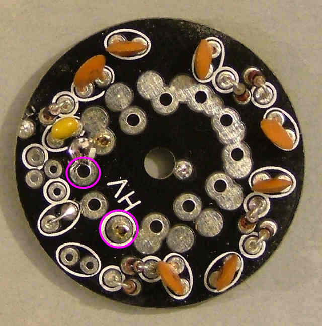
Fit two pins as shown and solder in place.

Image

Make four of these for use with 4x IN-15Bs: Bishops
Tony
Site Admin
Posts: 948
Joined: Tue Jul 24, 2012 8:05 pm

Re: Piece display PCB

Post by Tony »

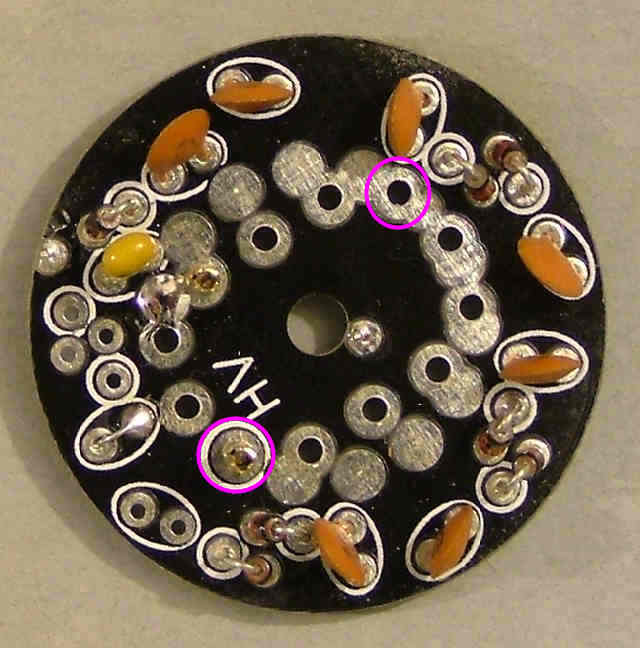
Fit two pins as shown and solder in place.

Image

Make four of these for use with 4x IN-15As: Knights
Tony
Site Admin
Posts: 948
Joined: Tue Jul 24, 2012 8:05 pm

Re: Piece display PCB

Post by Tony »

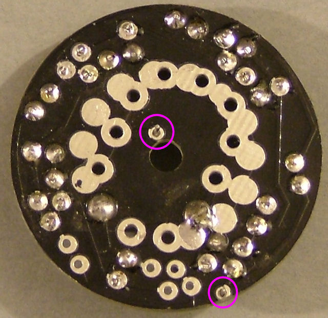
Examine the board for bridges and errors. Once you're sure it has been assembled correctly solder two thin wires here:
Image

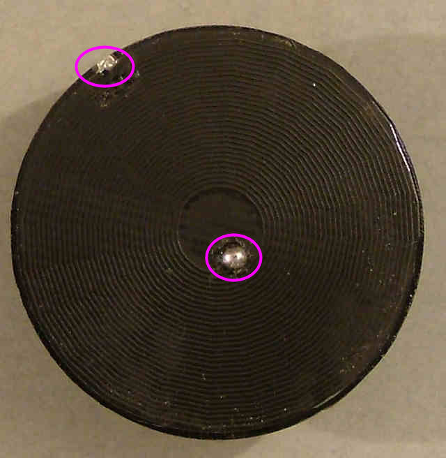
Take one of the printed coil PCBs and solder it to the two wires using the smallest neatest possible joint.
Image

Plug a suitable nixie tube for the board into the two pins, the anode can be identified by the white ceramic coating on the inside of the tube. This connects to the 'HV' pin.

Now repeat for the other 31 pieces :o
Locked