PCB assembly - BAG2
PCB assembly - BAG2
Time to start on Bag 2, but first take a few minutes to go back through the instructions and double-check you've got eveything in the right place. Correcting mistakes will get harder from here on.
Re: PCB assembly - BAG2
Fit the first plastic IR LEDs in the space marked D1 and D17 as shown. These may be 3mm or 5mm LEDs. NOTE these are polarised and must be fitted the right way round. There is a flat mark on the side of the LED body,
For D1 but the flat side faces to the LEFT of the PCB when viewed as shown in the photograph.
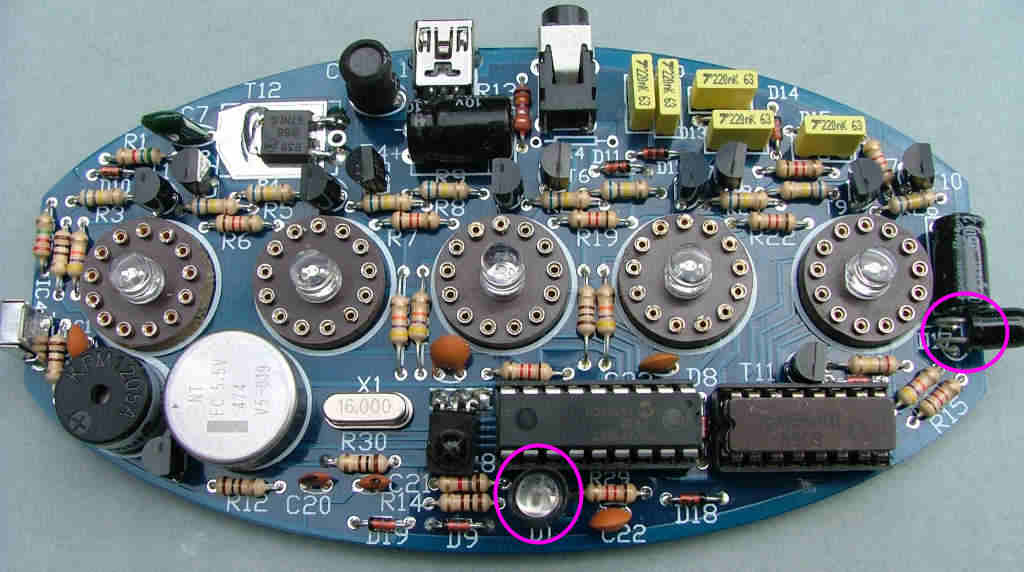
For D1 but the flat side faces to the LEFT of the PCB when viewed as shown in the photograph.

Re: PCB assembly - BAG2
Take the clear plastic IR LED and bend the leads as shown - the flat mark on the LED body must face away from you when bending them and to the top/rear of the PCB when it's fitted:
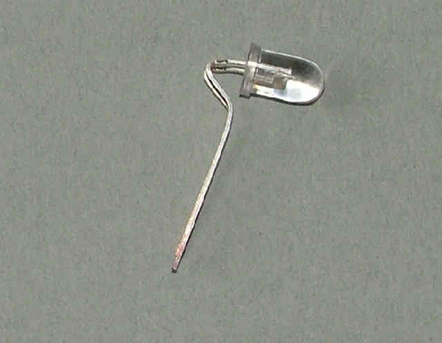
Solder it in the place marked for D17. The leads need to be flexible enough to allow it to be pointed out of the case when it's assembled.
Solder it in the place marked for D17. The leads need to be flexible enough to allow it to be pointed out of the case when it's assembled.
Re: PCB assembly - BAG2
Fit the IC sockets SK3 and 4 into the positions marked for IC1 and IC2 making sure BOTH the notches face D8 as marked on the PCB.
Fit IC3 and IC4 (the domed black plastic 3 legged blocks). IC3 is flat against the PCB and IC4 is vertical and faces to the left. If they are both black plastic, IC3 is the one with a cross on the lens.
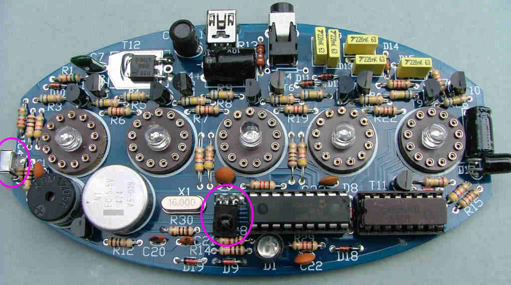
Fit IC3 and IC4 (the domed black plastic 3 legged blocks). IC3 is flat against the PCB and IC4 is vertical and faces to the left. If they are both black plastic, IC3 is the one with a cross on the lens.

Re: PCB assembly - BAG2
Fit T12 (the square black plastic 3 legged part), bending the end 3mm of its legs down 90 degrees to fit in the holes. Make sure it lies flat on the PCB and solder the tab on the top first, then the three legs.
DON'T FORGET TO SOLDER THE TAB! it acts as a heatsink connection to the PCB.
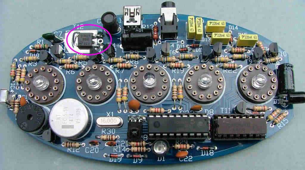
DON'T FORGET TO SOLDER THE TAB! it acts as a heatsink connection to the PCB.

Re: PCB assembly - BAG2
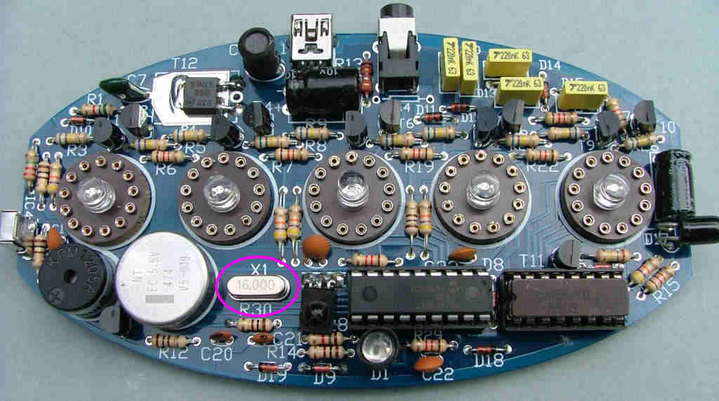
Solder X1 (the 16.000 crystal) into the 2 pads marked for X1:

Re: PCB assembly - BAG2
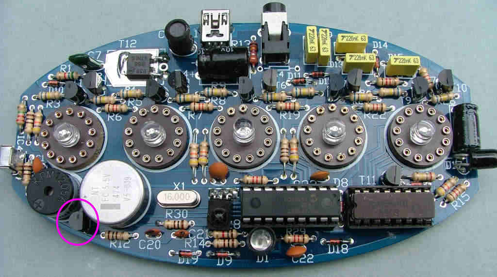
Now fit T13 (2N7000) - it looks the same as T1-11 so was packed in the second bag to avoid it being mixed up. The flat edge faces RIGHT.

Re: PCB assembly - BAG2
Now it's finally time to try power for the first time. Connect a multimeter on a current range (about 0-500mA) between the pads where R13 will be - this is just to the right of C8. Connect the + red lead to the topmost pad and the - black lead to the lower pad. Plug in the USB power supply and switch on.
You should have a reading of a few mA which rapidly drops to almost nothing as C8 charges. Switch off and disconnect everything. If the test was OK move onto the next stage, if not check for solder bridges. If there was no reading at all make sure your meter is working and connected correctly.
You should have a reading of a few mA which rapidly drops to almost nothing as C8 charges. Switch off and disconnect everything. If the test was OK move onto the next stage, if not check for solder bridges. If there was no reading at all make sure your meter is working and connected correctly.
Re: PCB assembly - BAG2
Fit IC1 (PIC 16F1827)
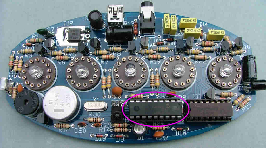
and IC2 (KM155ID1)
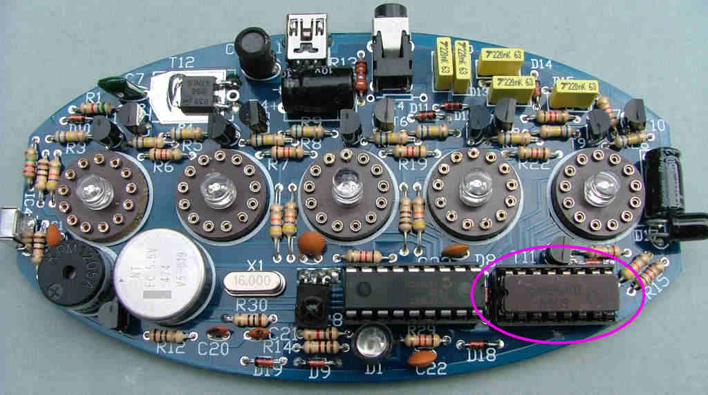
into their sockets (you'll probably need to trim about 1/8" off the leads of IC2) and reconnect the multimeter and USB supply. Make sure both notches point towards D8, IC1 is 'upside down' relative to IC2.
This time the current reading should be about 20-25mA and the 5 blue LEDs will light up, flickering slightly.
If it's reached this stage you now know the CPU is running and there aren't any major assembly problems on the low voltage side.
Now test the IR detector is working - hold your hand about 6" above the clock for a few seconds - there should be a beep and LED D3 will go out. If not check around IC3 and If not try using a phone camera to view D1 to make sure it's lighting up. If it's not, check you have it fitted the right way round. You may need to temporarily fit the piece of heatshrink sleeving over LED D1 for it to work.

and IC2 (KM155ID1)

into their sockets (you'll probably need to trim about 1/8" off the leads of IC2) and reconnect the multimeter and USB supply. Make sure both notches point towards D8, IC1 is 'upside down' relative to IC2.
This time the current reading should be about 20-25mA and the 5 blue LEDs will light up, flickering slightly.
If it's reached this stage you now know the CPU is running and there aren't any major assembly problems on the low voltage side.
Now test the IR detector is working - hold your hand about 6" above the clock for a few seconds - there should be a beep and LED D3 will go out. If not check around IC3 and If not try using a phone camera to view D1 to make sure it's lighting up. If it's not, check you have it fitted the right way round. You may need to temporarily fit the piece of heatshrink sleeving over LED D1 for it to work.