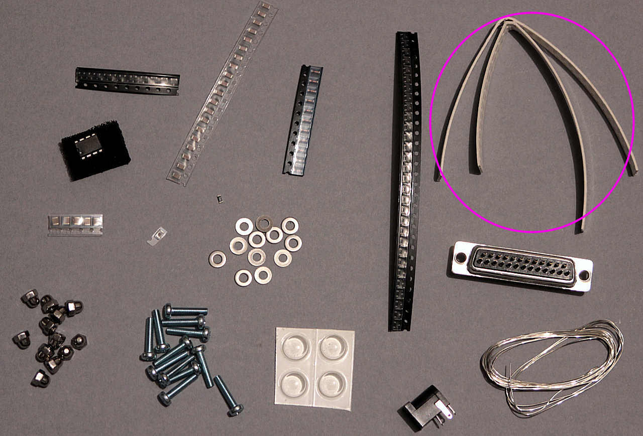
If you received the through-hole board PCB (Red PCB) you'll have nine pre-assembled piece PCBs. These only have 2 pads and are intended to be connected to the tube via short insulated wires. Skip down to the 'D-socket' post.
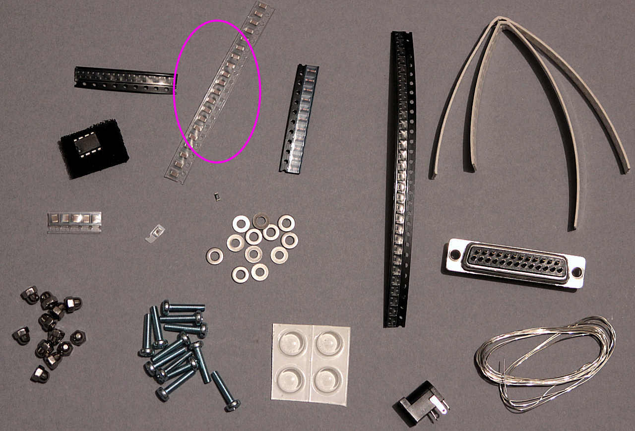
For this you will need the BAV99 diode strip, 10n capacitor strip(s), 1n capacitor strip, the BAV103 strip and the 9x circular PCBs supplied bolted together. Enough components should be included for 10 PCBs though only 9 are built.
30x Diode packs - Three legged black rectangles with text etched on the top surface. These are polarised and must face the same way as in the photographs with the text facing up.
10x Glass Diodes - Copper-orange glass cylinders with a black band marking one end. These are polarised and must face the same way as in the photographs.
70x 0.1uF Capacitors - Beige rectangles with solder on either end, not polarised. Seven of these are used on each board.
10x 1nF Capacitors - Grey rectangles with solder on either end, not polarised. One of these is used on each board.
Piece base PCB
Re: Piece base PCB - SMD version
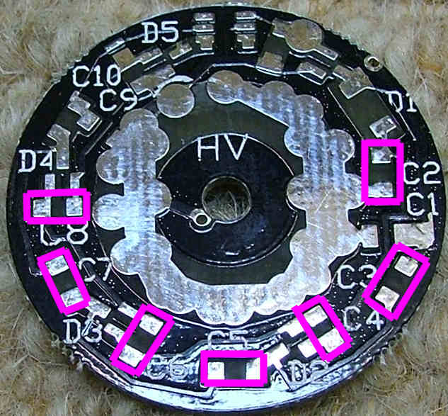
First fit the 7x 0.1u ceramic capacitors:
Note that you may find it easier to fit the diode packs first, it's up to you.
Re: Piece base PCB - SMD version
Next the 3 diode packs, they can only fit one way round if you make sure the text is facing up:
Re: Piece base PCB - SMD version
Next the glass diode, the band FACES C2:
Re: Piece base PCB - SMD version
Next the 1n tuning capacitor, this is grey compared to the beige 0.1u multiplier caps:
Re: Piece base PCB - SMD version
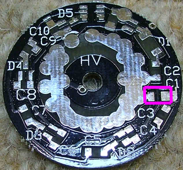
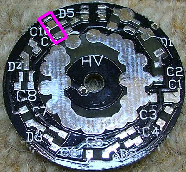
Finally using fine wire or solder, bridge these pads:
Re: Piece base PCB - SMD version
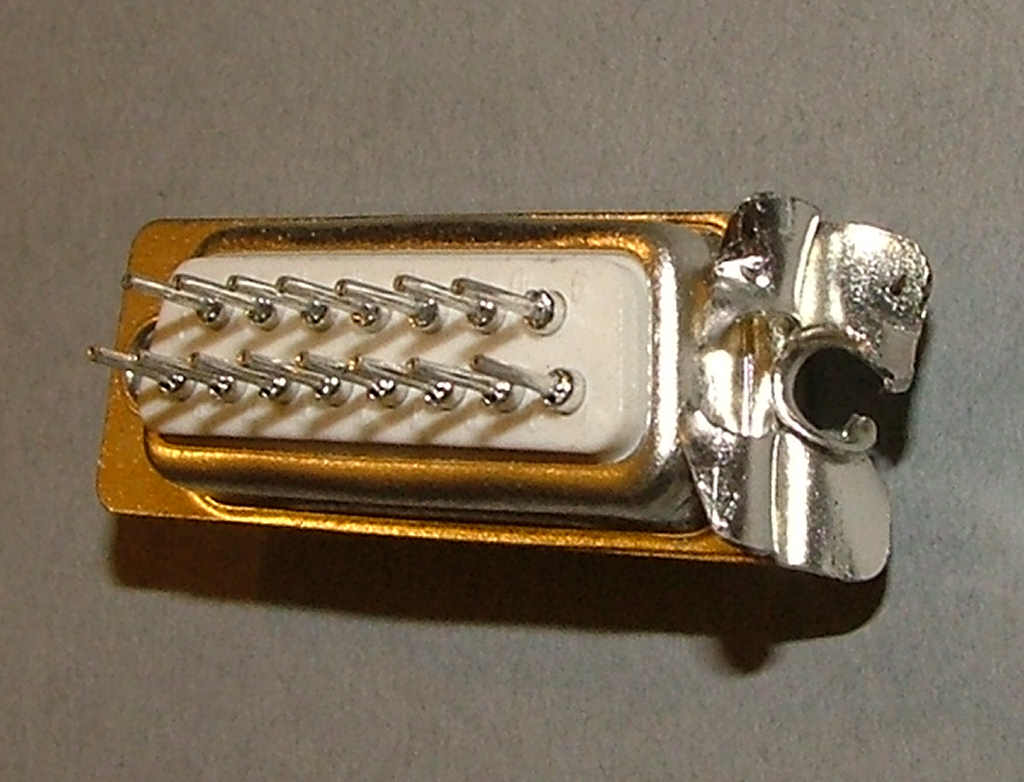
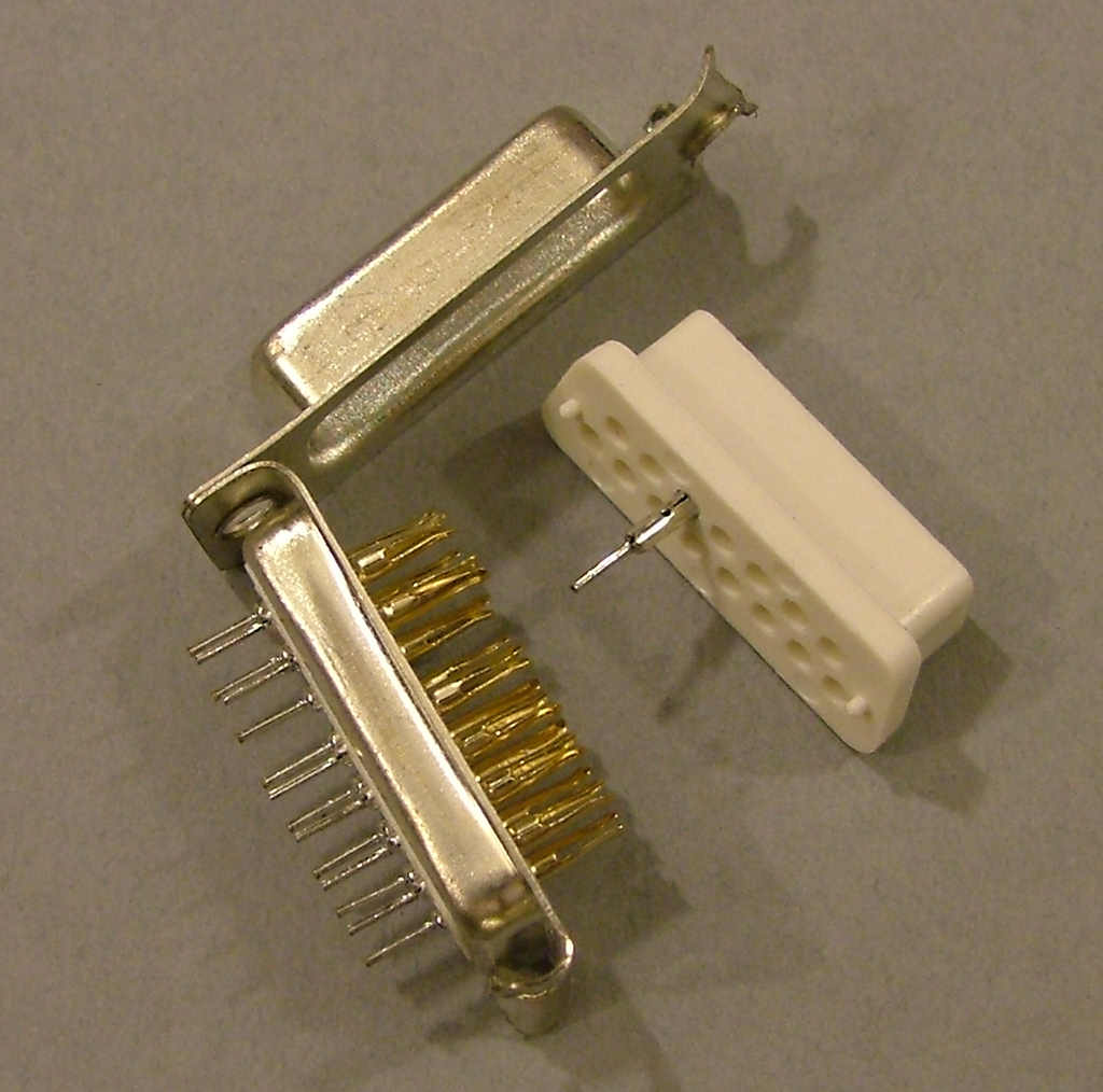
Dismantle the 25 way 'D' socket, the easiest way is to cut through one of the rivets then seperate the two halves of the shell.
Open up the socket housing and remove the pins.
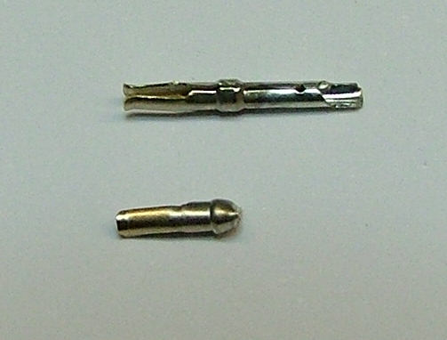
Cut the pin leg, just below the 'bump' under the contacts:
For the pre-assembled piece boards, cut 18 short pieces of thin 'hookup wire', about 2.5-3cm long. Strip and tin each end then solder one of the above trimmed socket pins onto one end of each of the 18 wires.
Place the piece PCB with the 2 large solder pads at about 10 and 2 o'clock then solder one wire to each of the 2 pads. Repeat for all 9 PCBs, using your 18 wires.
Connect the wire from the left pad to the tube anode and the wire from the right pad to the tube cathode, as in the instructions below.
This method makes it much easier to assemble rather than having to try and hold the pins onto the PCB in the correct position and vertacal whilst soldering them.
Re: Piece base PCB - SMD version
Tin the cut end of 2 pins then put a blob of solder on the pads shown here:
Using tweezers, hold the pin over the solder blob and melt it. Push it into the solder and hold in place until set.
Looking from under the nixie, pins are counted clockwise from the gap
with the first to the right of it being pin 1.
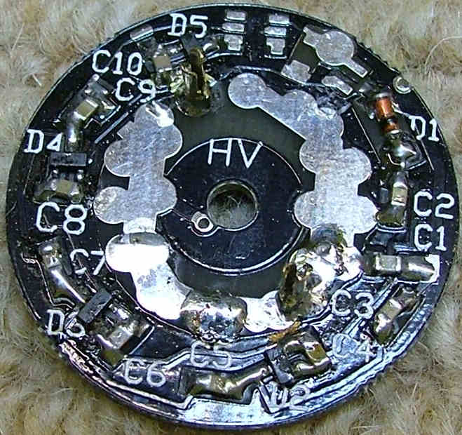
Make four of these for use with 4x IN-7A/IN-7 for the '+'. pin 2 is connected to the pad marked 'HV' and pin 4 to the pad
next to D4.
Re: Piece base PCB - SMD version
Tin the cut end of 2 pins then put a blob of solder on the pads shown here:
Using tweezers, hold the pin over the solder blob and melt it. Push it into the solder and hold in place until set.
Make five of these for use with 5x IN-7b: ohm
Using tweezers, hold the pin over the solder blob and melt it. Push it into the solder and hold in place until set.
Make five of these for use with 5x IN-7b: ohm
Re: Piece base PCB
If you have the later kit with IN-4 nixies use this picture - note the right-hand pin is slightly to the left of the pad on the PCB to allow the correct pin spacing.
The IN-4 is used for the '0' and has pin 10 connected to HV and pin 8 to
ground, which is the pad to the right. Again you'll need five of these.
The IN-4 is used for the '0' and has pin 10 connected to HV and pin 8 to
ground, which is the pad to the right. Again you'll need five of these.