From mid-2018 the PCB is RED with through-hole parts, much easier to assemble than the earlier SMD board.
If you received this version please go to the 'Board PCB - Red version' thread.
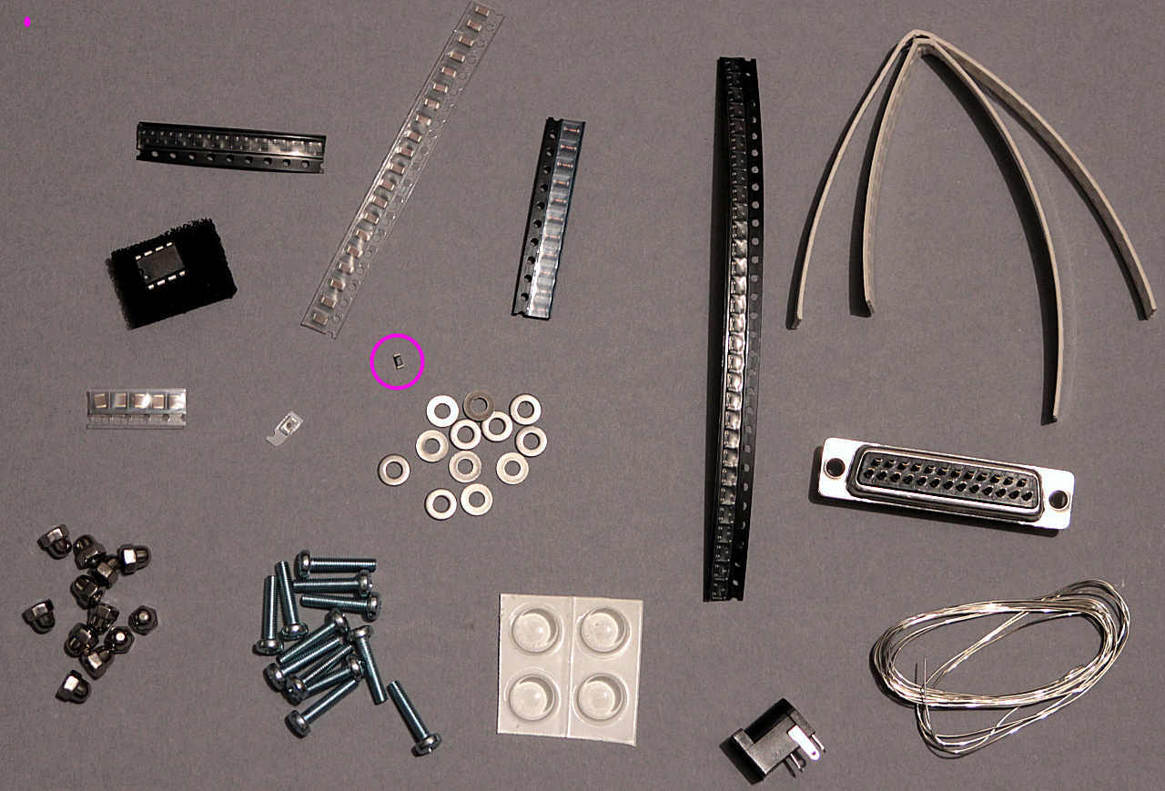
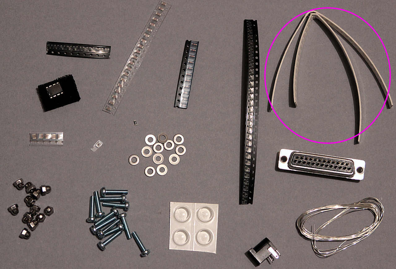
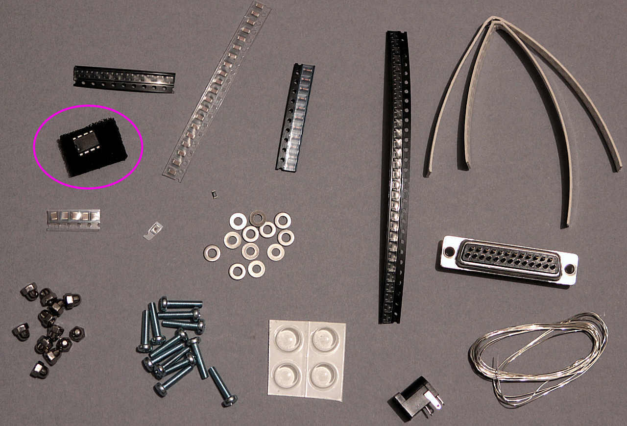
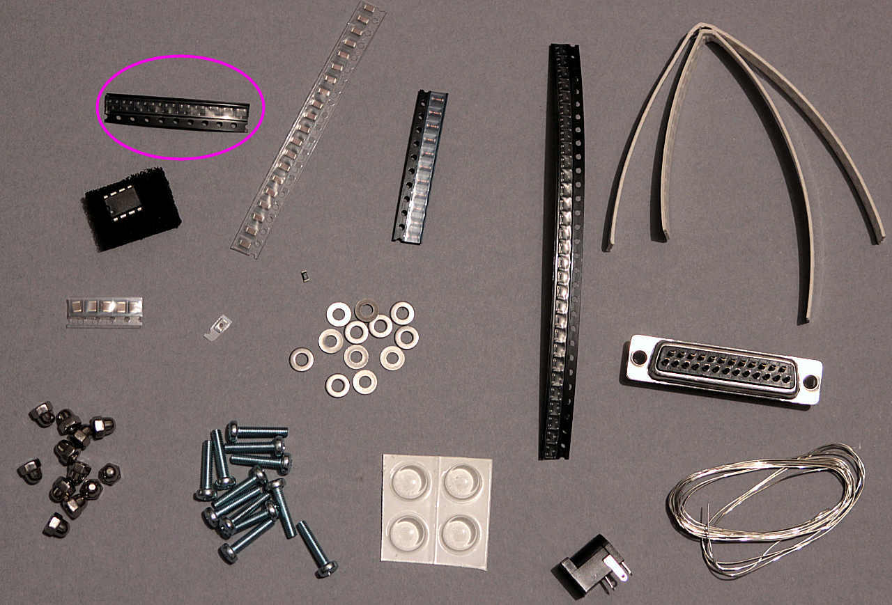
Unpack the component bag and sort them out into separate piles. You should have:
9x 2n7002 transistors (3 legged rectangles) These must be fitted the right way round.
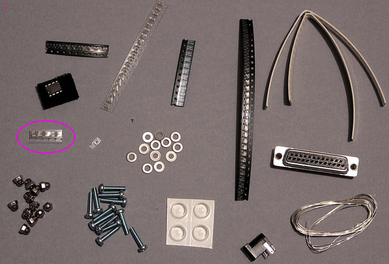
18x 1n ceramic capacitors (grey ceramic)
9x BAV99 diodes (glass beads)
27x BAV103 diodes (3 legged rectangles, don't mix them up with the transistors) These must be fitted the right way round.
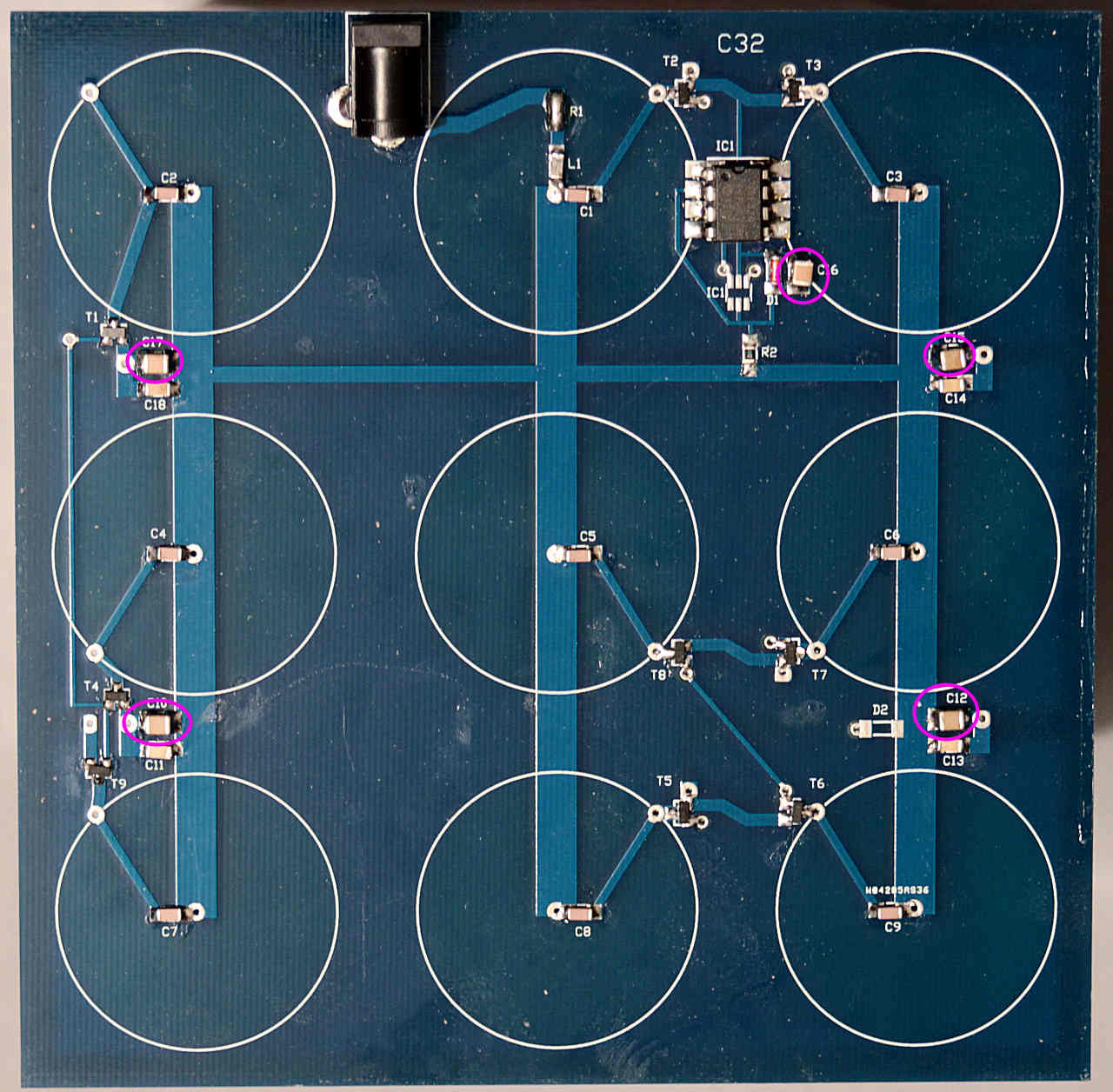
70x 100n capacitors (brown ceramic)
5x 10u capacitors (large brown ceramic)
1x 100R resistor (black rectangle with printed white number) - not in the latest batch.
1x 25 way D socket, for tube pins
12x M3x16 bolts, M3 washers and M3 dome nuts for case assembly.
4x rubber feet
5g solder
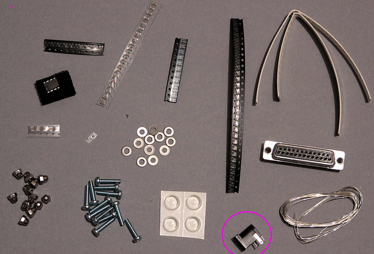
1x 3.1mm socket
Only some of these are needed here, most are used for the display piece PCBs and the hardware for the case.
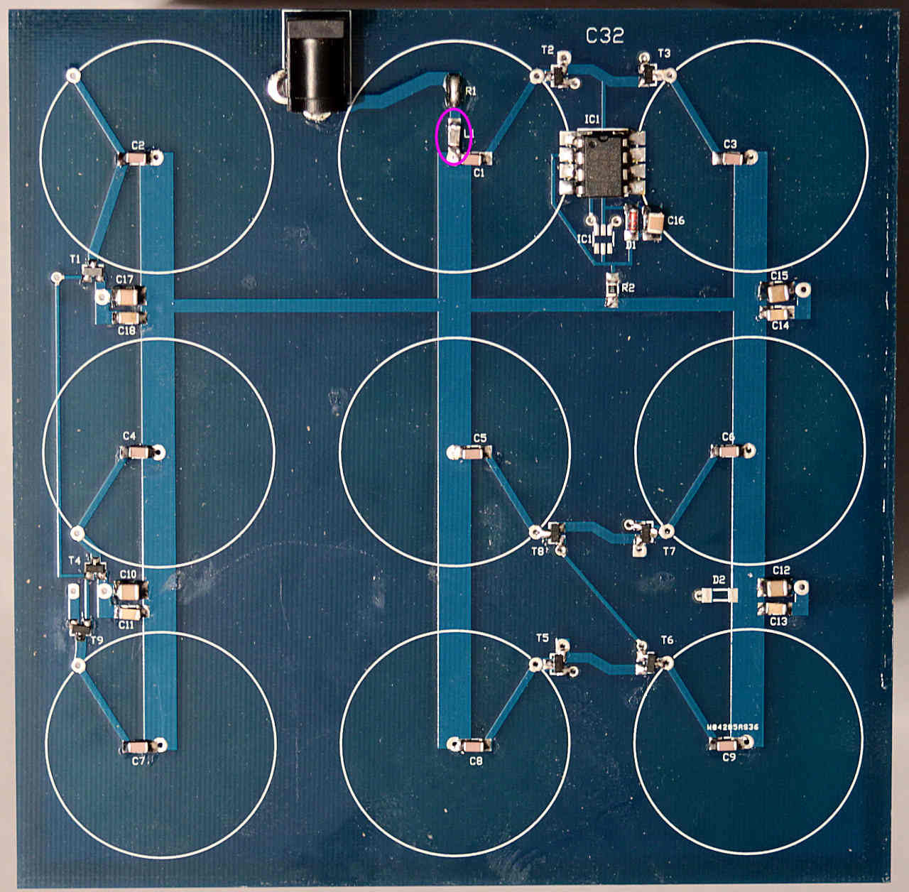
Start by bridging the pads for R1
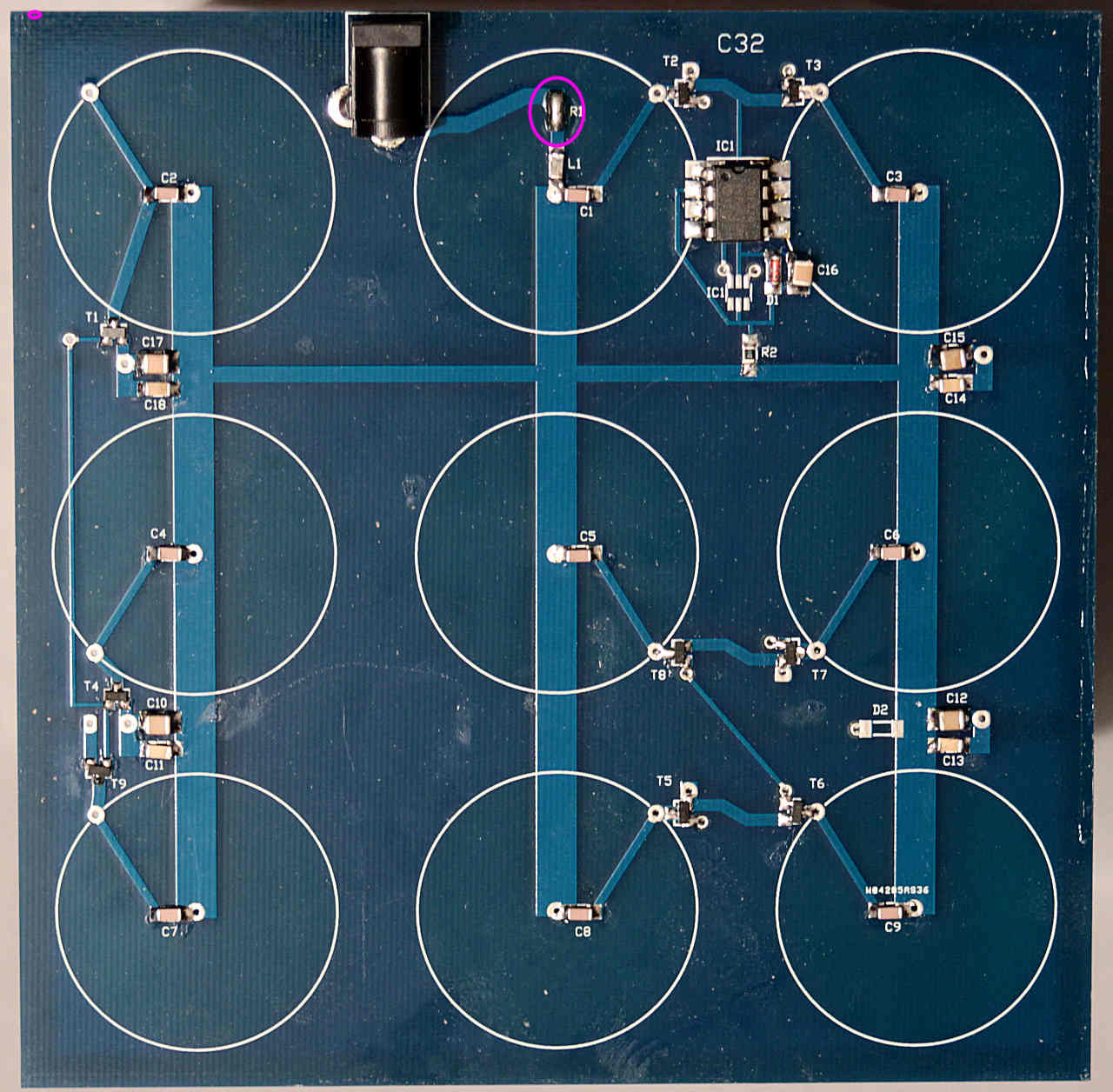
Board PCB
Re: Board PCB
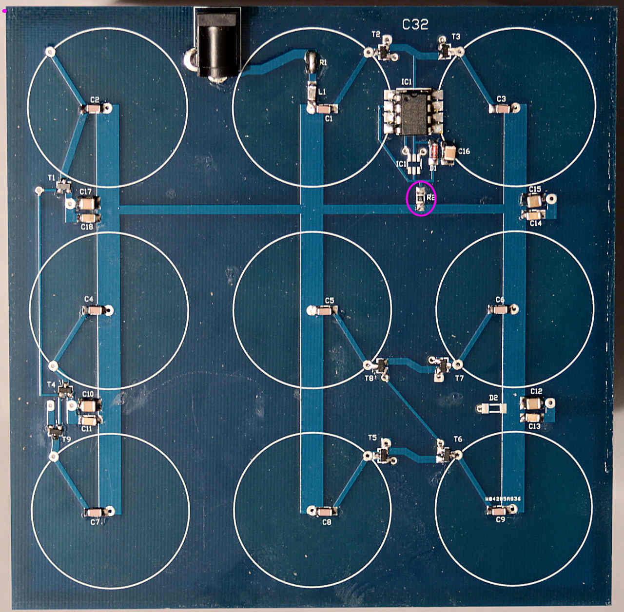
Followed by the 100R resistor if you have an early kit, if you received a later kit just bridge it with solder - the supply is 5V and it does nothing useful:
Re: Board PCB
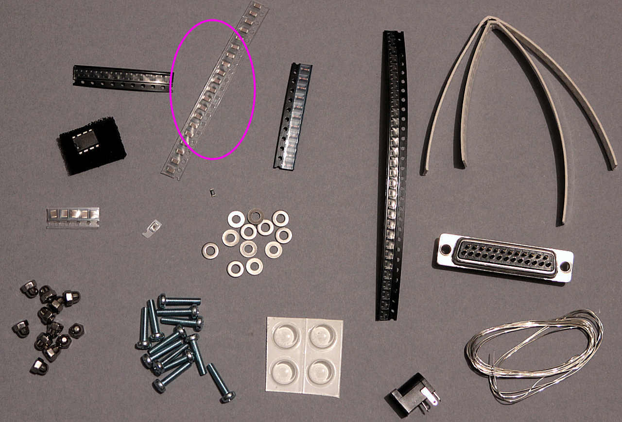
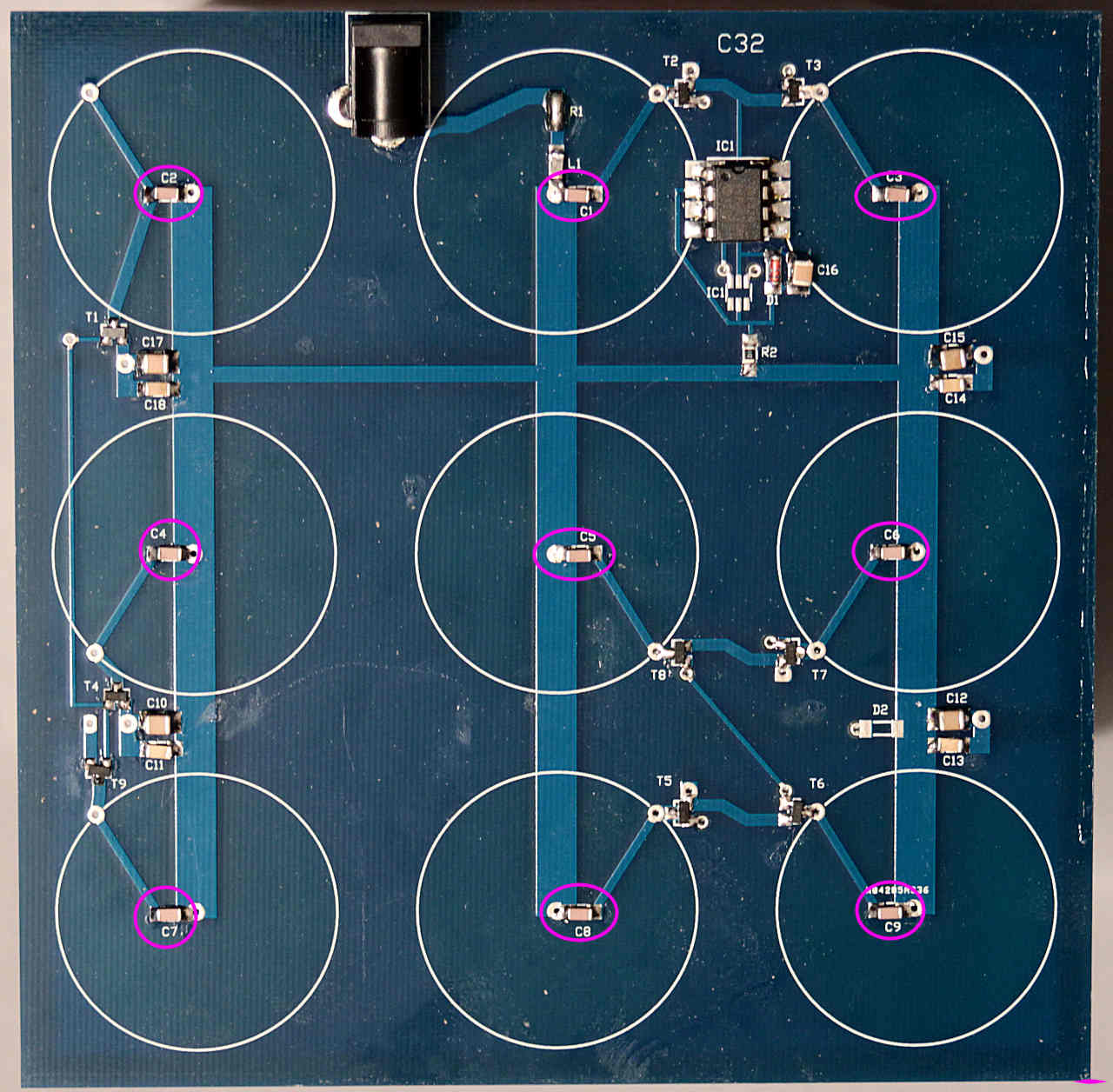
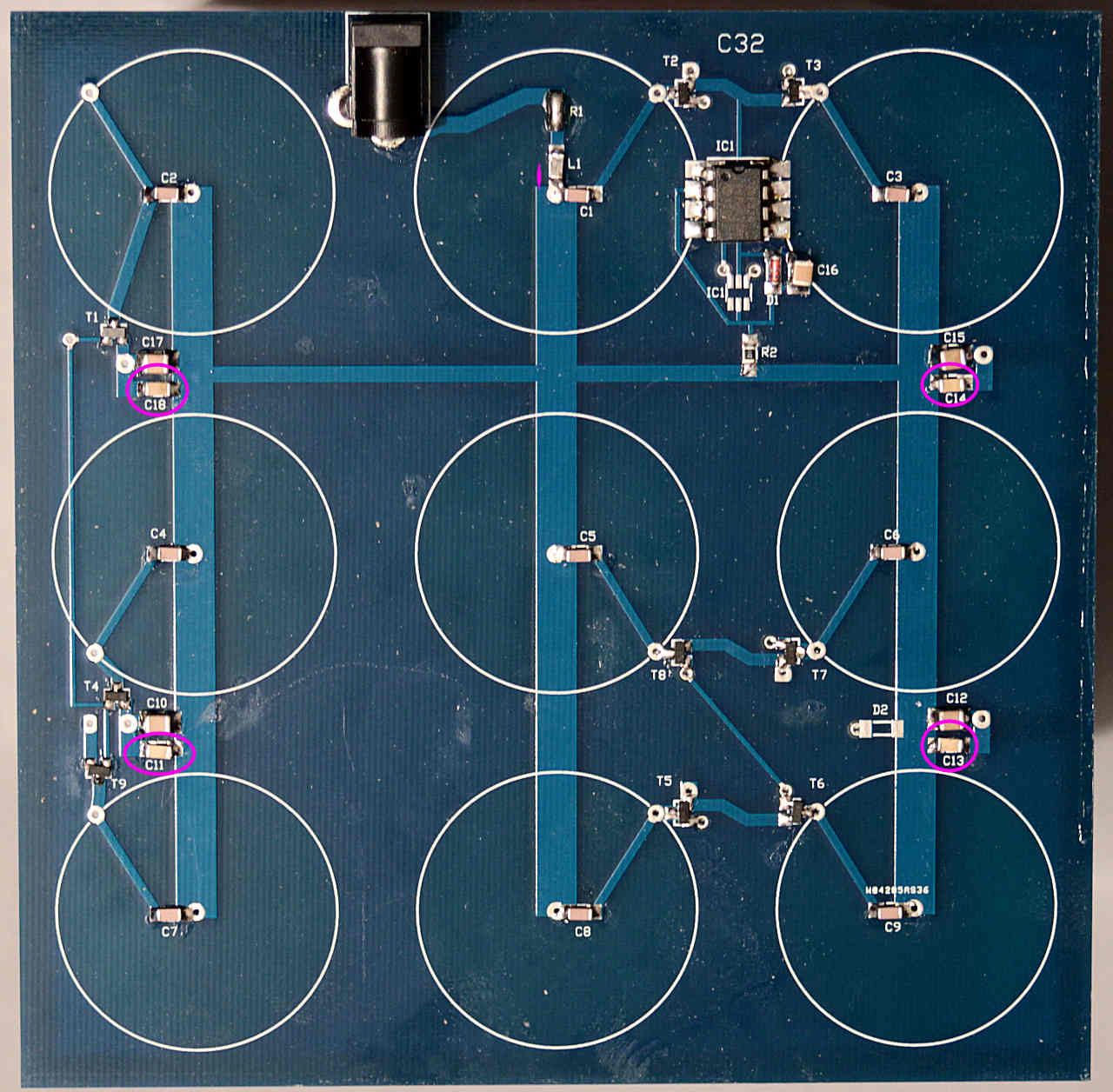
Next the 1n tuning capacitors, one for each coil:
Re: Board PCB
A few of the 100n capacitors are used here:
Re: Board PCB
Now the 10u capacitors:
Re: Board PCB
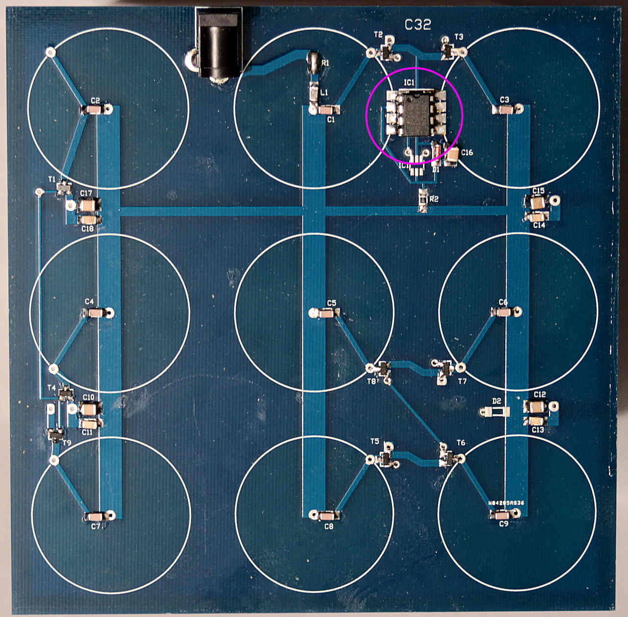
Now solder the PIC controller IC on. You'll need to bend the pins under the IC in a 'squashed bug' shape, then use it as a surface mounted device. You really don't want to have to use the real SMD version of this processor.
Re: Board PCB
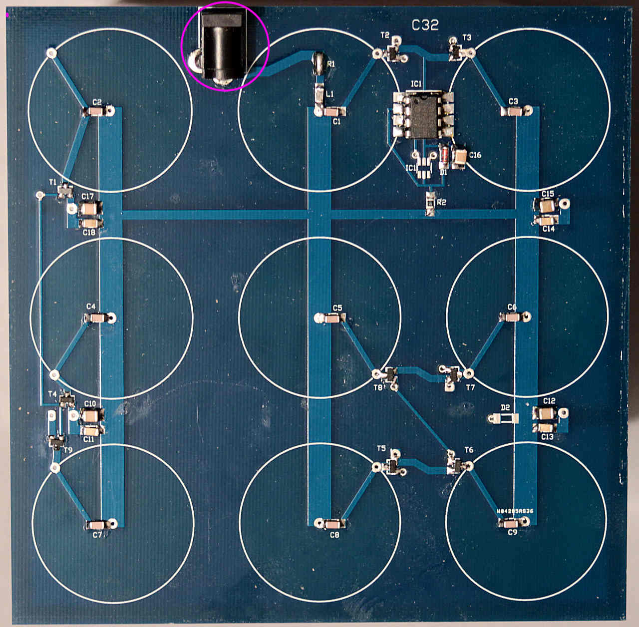
Solder in the power socket, making sure it's flat against the PCB. You'll need to trim the leads once soldered as there's only 1.5mm clearance when the case is assembled:
Re: Board PCB
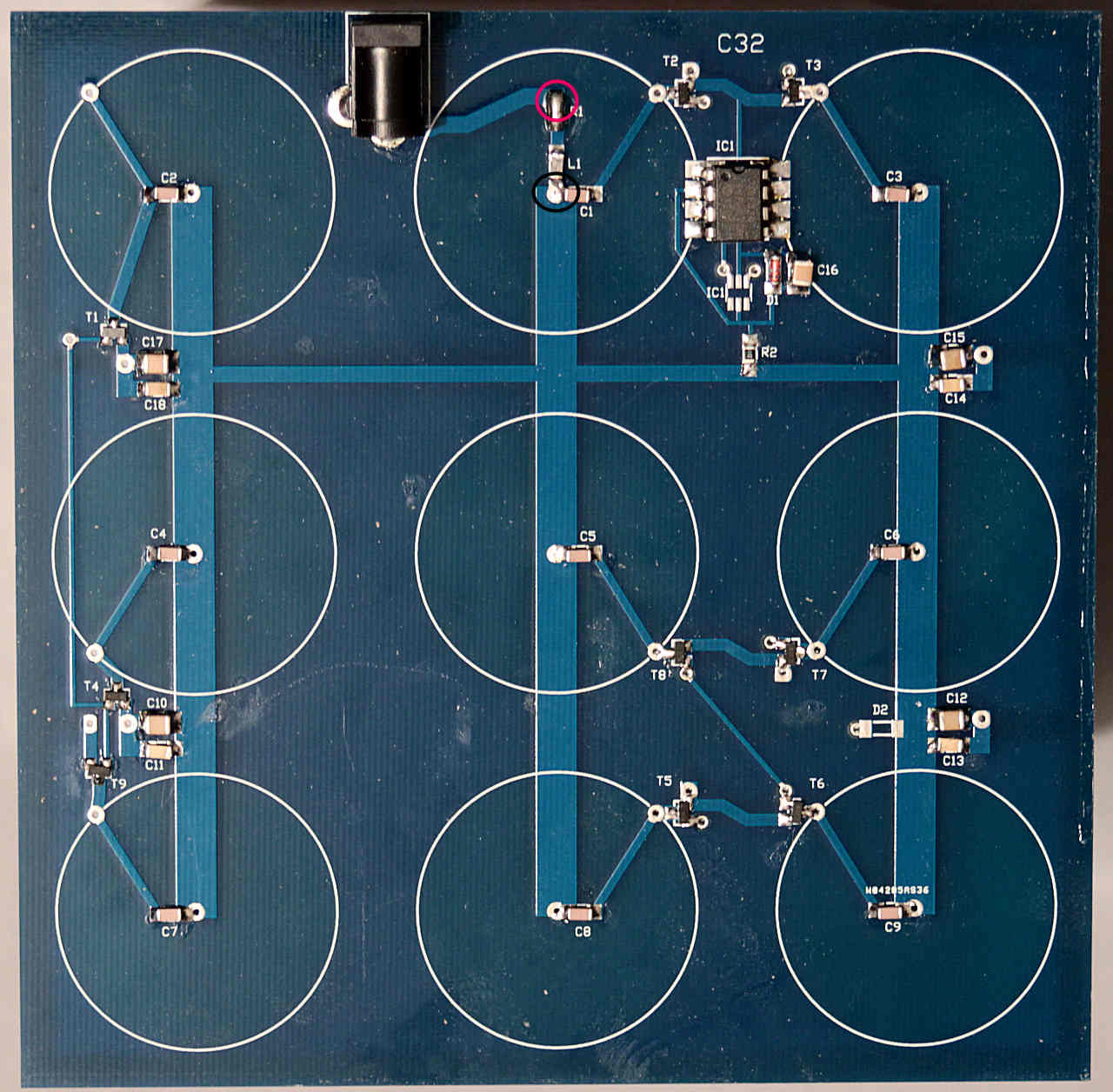
Solder 2 wires or wire offcuts to the 2 points marked to allow a multimeter to be connected:
It's time for the first taste of power!
Connect a meter set on 0-500mA or close range to the 2 wire test points, + to the R1 bridge and - to the L1 pad. Connect the power supply and switch on carefully for a few seconds.
You should have a reading of less than 10mA, if not check for solder bridges.
Note that D1, shown in the pictures, isn't used in the final version as the power supply provides a stable 5V supply.
Re: Board PCB
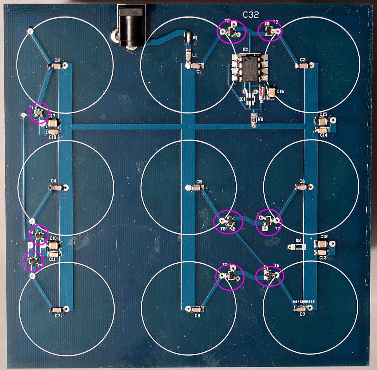
The driver transistors are next, these must be fitted with the engraved text side facing up:
I'd recommend fitting 2-3 at a time, then making another power-up test. You should see the reading increase by about 70-80mA for each transistor. Remeber to disconnect the power supply from the PCB before soldering each batch.
Re: Board PCB
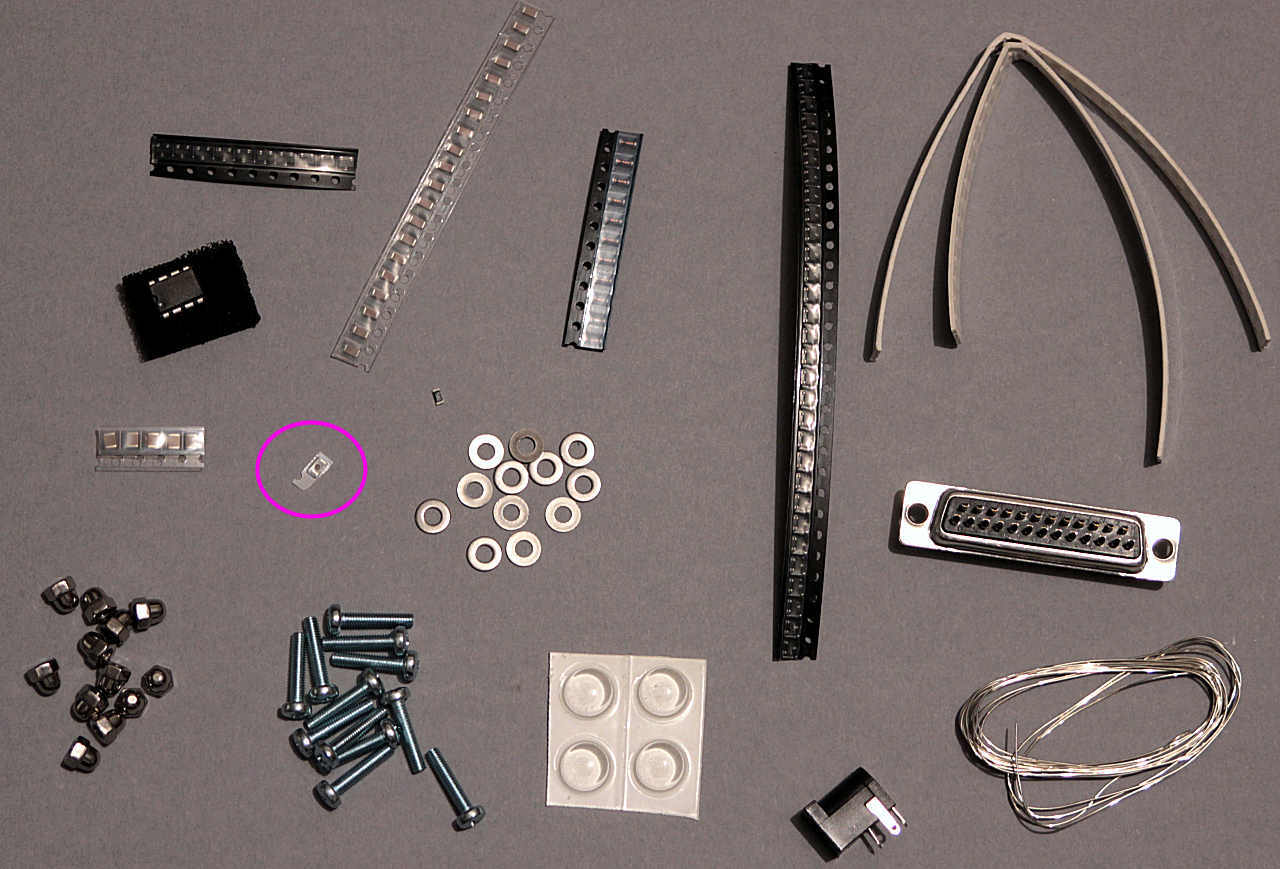
Once all 9 transistors are fitted you should have a working base board drawing about 6-700mA and you can remove the 2 test point wires. The final component is a ferrite filter, L1. Later kits don't use this so just bridge with solder: