Page 2 of 3
Re: 2 - PCB Assembly
Posted: Sat Dec 02, 2017 5:43 am
by Tony
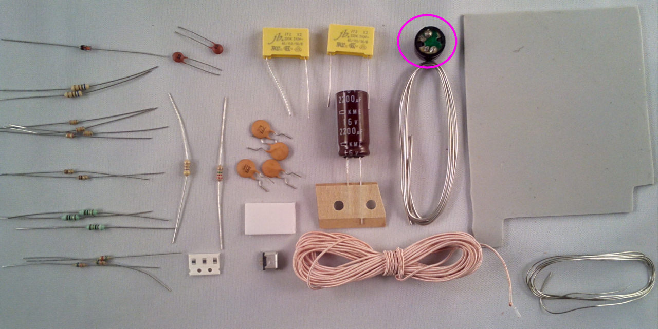
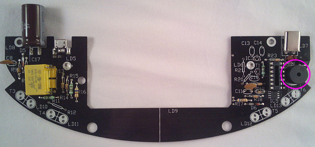
Speaker LS1, the + points to the top right:
Re: 2 - PCB Assembly
Posted: Sat Dec 02, 2017 5:47 am
by Tony
The USB socket - it's fitted so the edge of the PCB sits between the 2 rows of pins, allowing them to be soldered to each side of the board. The 3-pin row is on the top side:
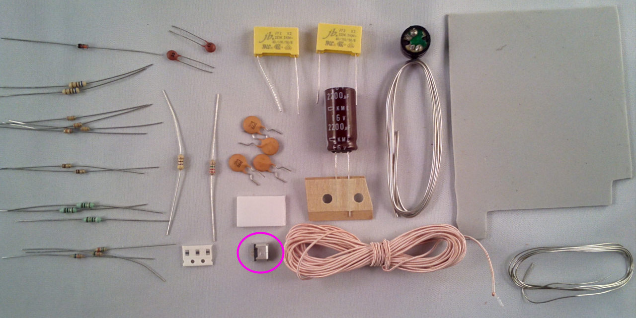
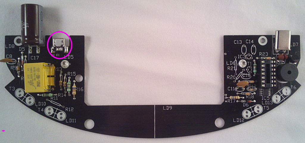
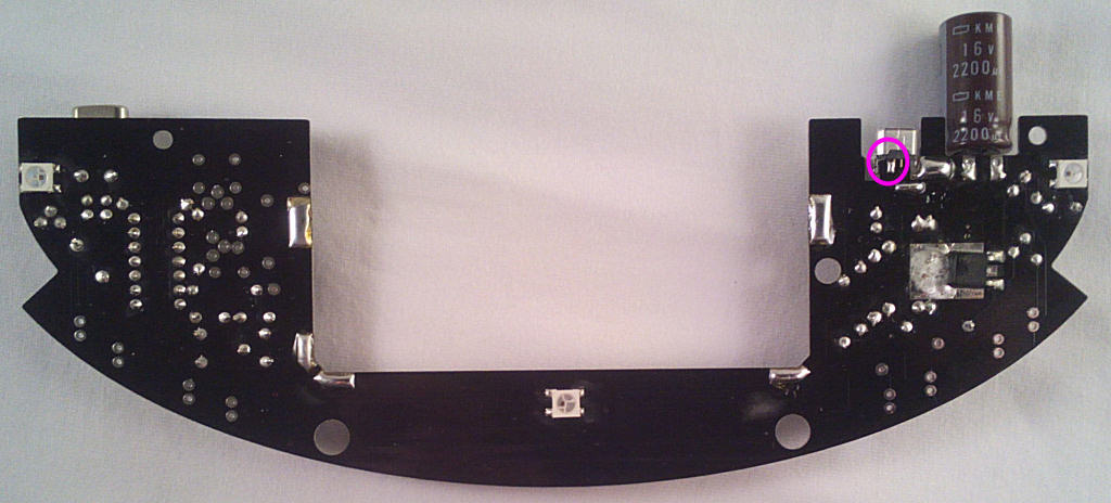
Solder the pins on both sides of the board and bridge the socket case to the board as shown - be careful the solder doesn't end up in the socket though.
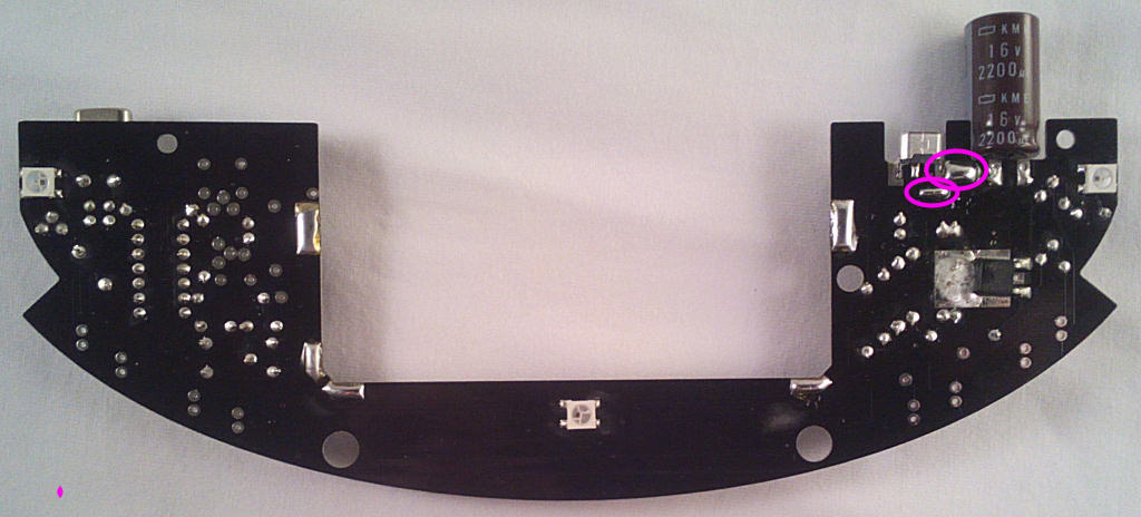
Bridge these pads with solder or component wire offcuts:
Re: 2 - PCB Assembly
Posted: Sat Dec 02, 2017 5:50 am
by Tony
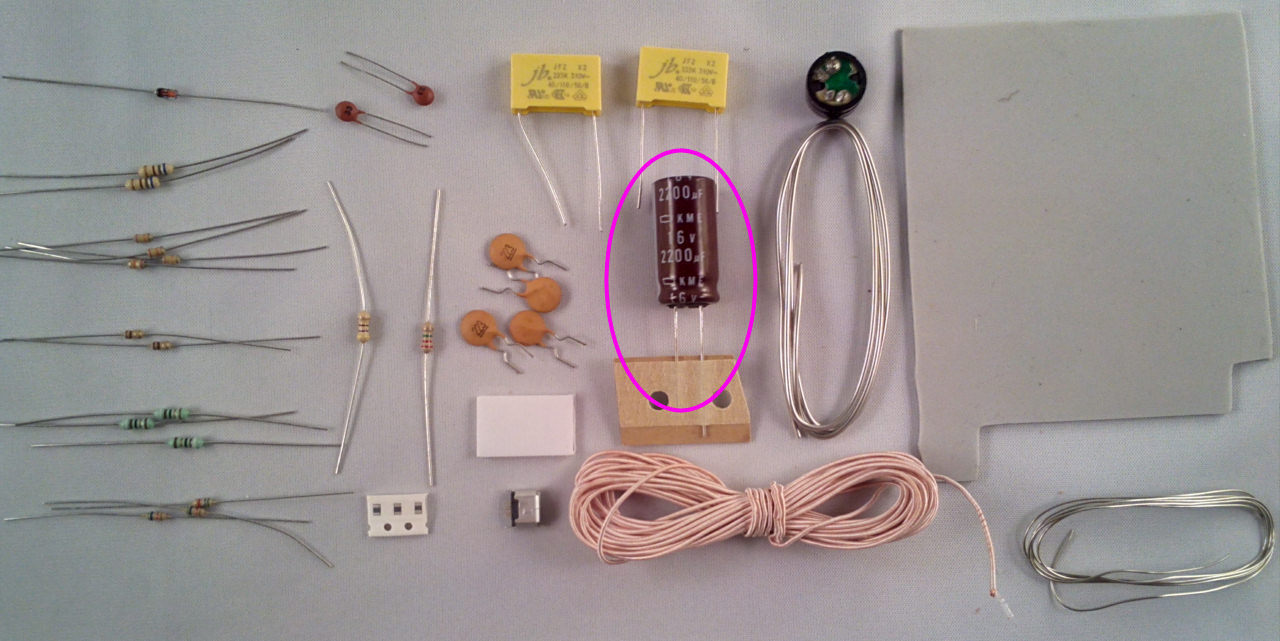
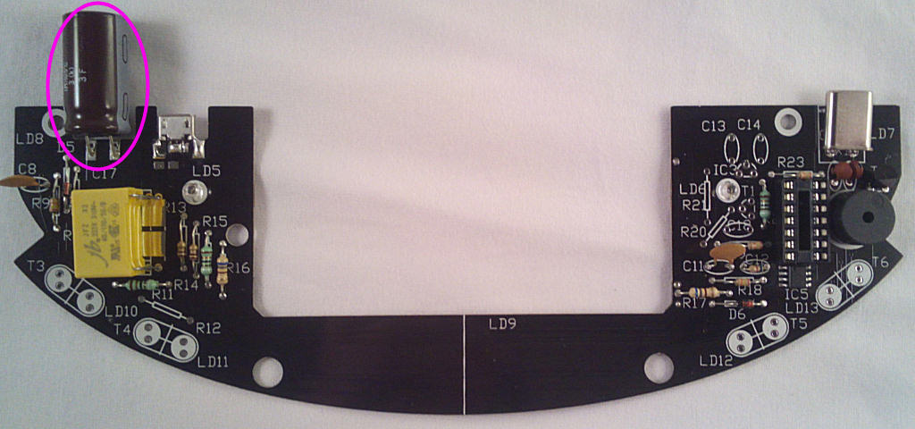
Now the last component from bag1 for now - the 2200u electrlytic capacitor. It's polarised so make sure the white band faces right:
Re: 2 - PCB Assembly
Posted: Sat Dec 02, 2017 6:26 am
by Tony
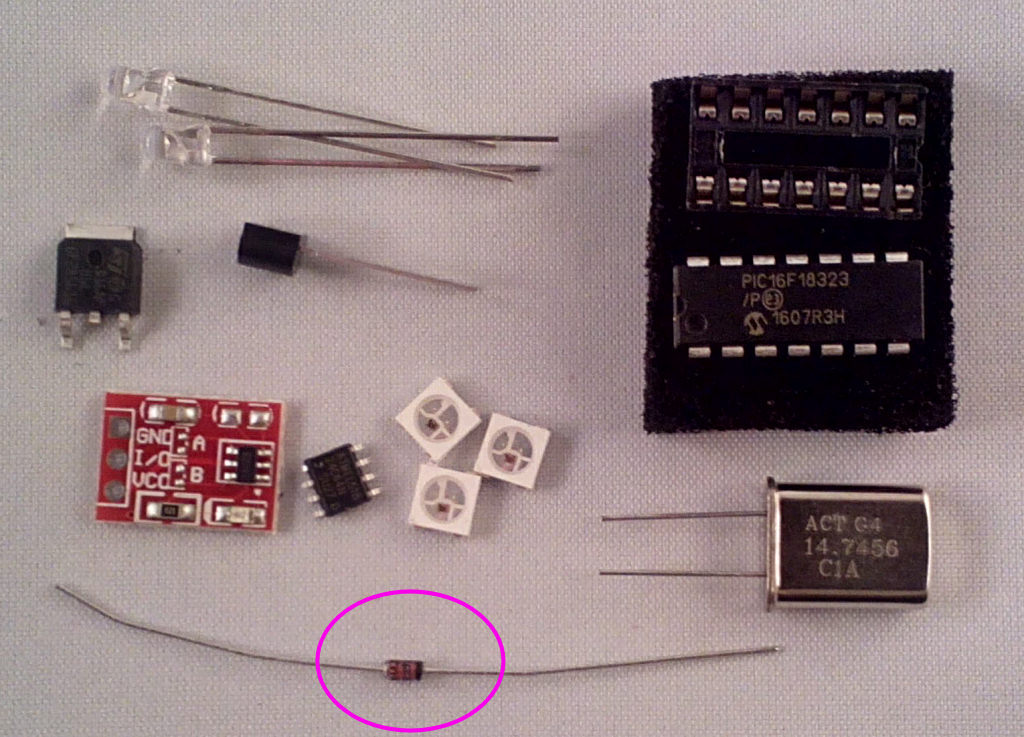
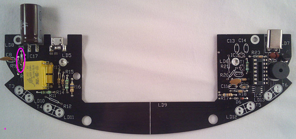
Bag 2 components next, starting with D5, the black band faces down:
Re: 2 - PCB Assembly
Posted: Sat Dec 02, 2017 6:29 am
by Tony
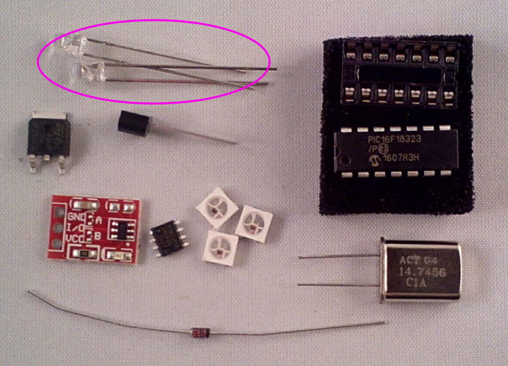
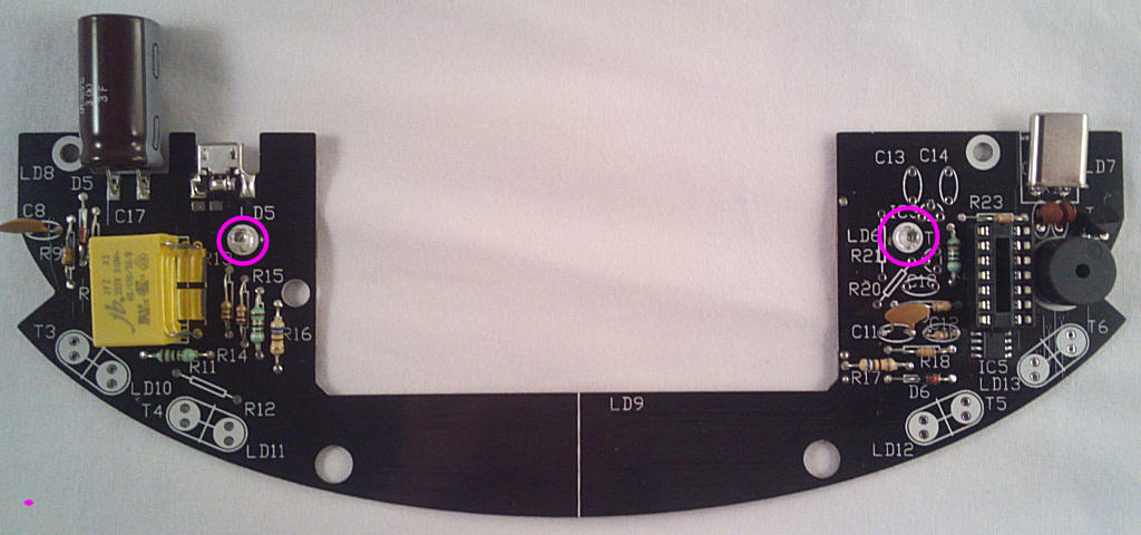
Then the 2x IR LEDs, LD5 and LD6. The SHORT lead points to the TOP of the board for both LEDs:
Re: 2 - PCB Assembly
Posted: Sat Dec 02, 2017 6:31 am
by Tony
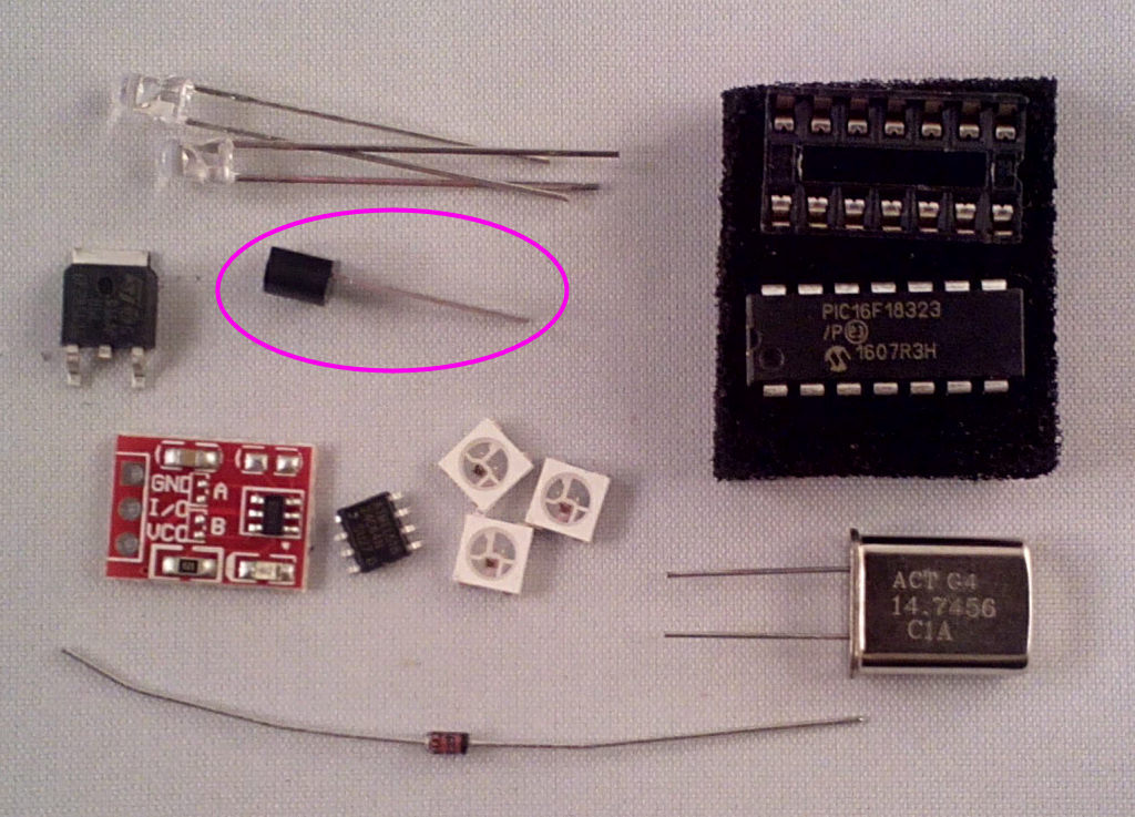
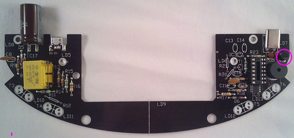
The 2n7000 speaker driver, T2
Re: 2 - PCB Assembly
Posted: Sat Dec 02, 2017 6:33 am
by Tony
The socket for IC4 - don't fit the IC yet though:
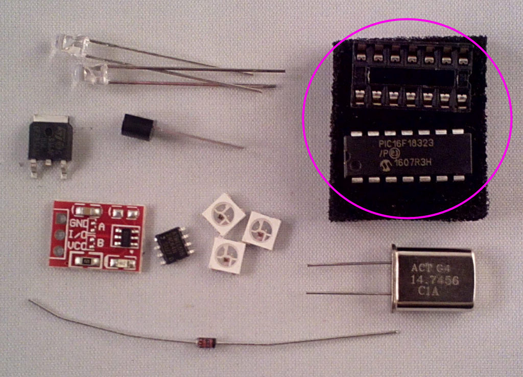
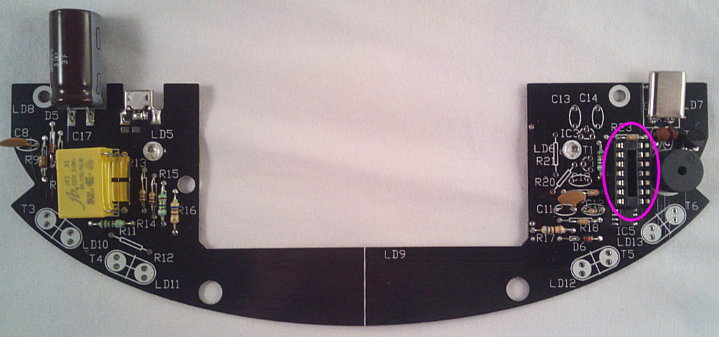
Re: 2 - PCB Assembly
Posted: Sat Dec 02, 2017 6:33 am
by Tony
Last part on this side for now is the crystal X1:
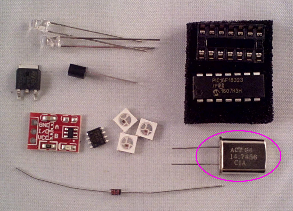
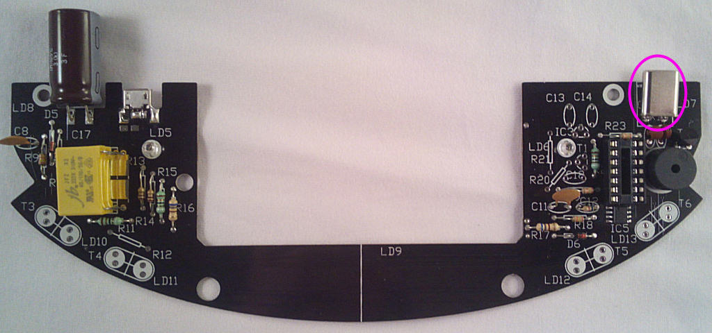
Re: 2 - PCB Assembly
Posted: Sat Dec 02, 2017 6:40 am
by Tony
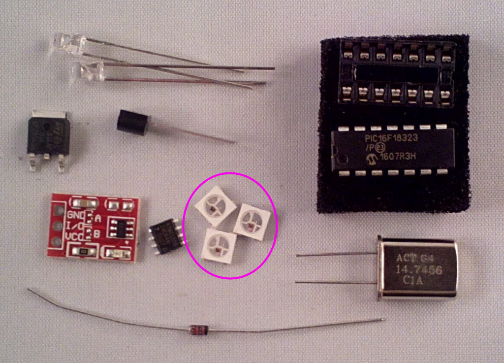
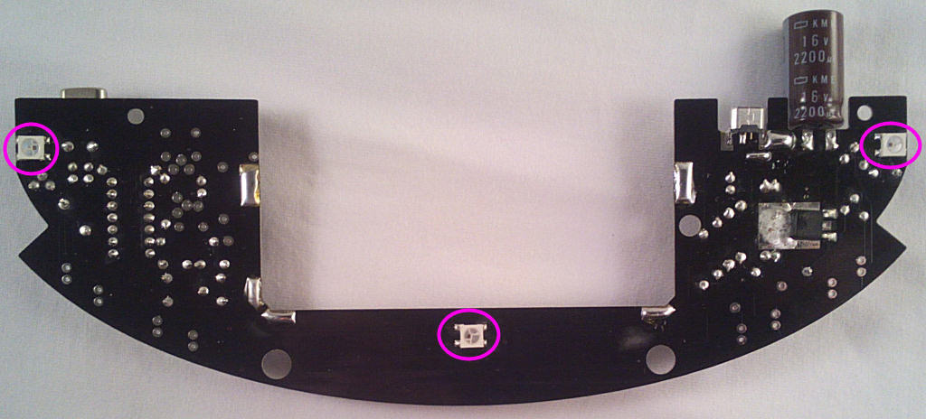
Time for a few surface mount parts, starting with the RGB LEDs LD7,8 and 9. The marked corner faces bottom right for LD7 and top left for LD8 and 9:
Re: 2 - PCB Assembly
Posted: Sat Dec 02, 2017 6:42 am
by Tony
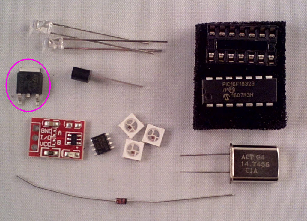
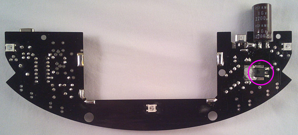
The coil driver transistor T7. Solder the tab and the 2 outer legs, the centre leg isn't used as the connection is made via the soldered tab. You did solder it?.
