Finally we need to make sure the drive signal is going to reach all the coil PCBs as a failure here will destroy the driver transistors on one or more coil PCBs.
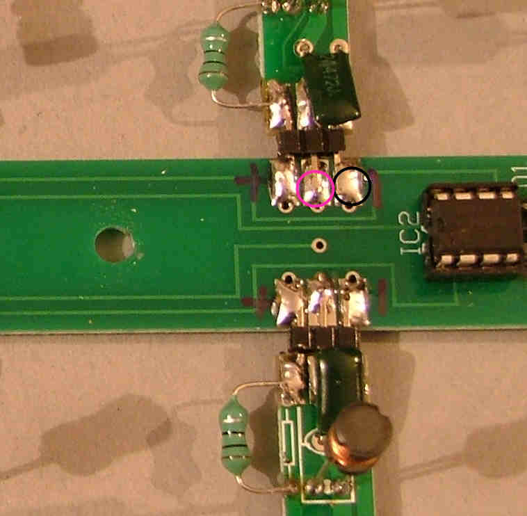
These are driven in pairs either side of the spine PCB and you'll need to check the voltage between the centre pin and ground of each pair as shown here:
Be VERY careful not to let the meter probe slip, if you short the centre driver pin to the 12V supply it will damage IC1 on that baord and possibly D1 and IC2.
Repeat for all 8 pairs of connections though you only need to test one side as they're linked together, depending on your meter the exact voltage will vary but should be about 2V.
Board PCBs
Re: Board PCBs
Now it's time to start on the driver PCBs themselves. Each of these has 4 coils and drivers and they are mounted in 8 pairs to form an array 8x8.
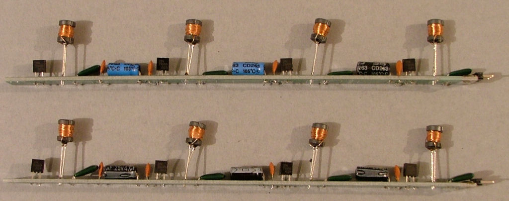
It's important to note that 8 of these are built with the components on the top of the PCB (the same side as the white silkscreen markings) and the other 8 are 'mirror images' built with the board upside down, with the silkscreen markings underneath. The following photographs show the pair of boards and construction is quite straightforward apart from the transistors which need to be reversed for the 'mirror' board.
First of all you need 4 of the green 4n7 capacitors for each board, fit these as shown for each of the pair of PCBs. These are not polarised and can go either way around:
Re: Board PCBs
Next the 14V zener diodes (the strip of 14 glass beads), fit these as shown for each of the pair of PCBs. These are polarised and the black band must face as shown:
These aren't needed on all the PCBs as they're just for overvoltage and reverse polarity protection. Use 10-12 of the diodes provided.
Re: Board PCBs
Now you need 3 of the black or blue 47u capacitors for each board, fit these as shown for each of the pair of PCBs. These are polarised and the black stripe must face the way shown:
Re: Board PCBs
Next 4 of the brown 10n capacitors for each board, fit these as shown for each of the pair of PCBs. These are not polarised and can go either way around:
Re: Board PCBs
Next the driver transistors (the 3 legged black things) 4 fro each board, the is where it can get a bit tricky. Fit these as shown for each of the pair of PCBs with the flat side facing the black band on the photo. The tricky bit is the position of the centre lead - on the bottom board with the silkscreen marking on top it's under the curved edge of the transistor but on the 'mirror' board it's sticking out from the flat edge:
Re: Board PCBs
Now cut a block of 3 pins from one of the header pin strips. Push the plastic spacer to about the halfway position and solder it onto the end of the PCB as shown:
Re: Board PCBs
Finally the coils themselves, as supplied they have a protective heatshink sleeve which needs to be removed. I found carefully cutting it with flat edge wirecutters to be easiest but be careful not to cut the copper wire underneath or damage the brittle ferrite base.
Fit these as shown for each of the pair of PCBs. These are not polarised but just push the wires far enough into the board to be soldered, leaing them as long as possible for later adjustment:
You may want to pre-bend them so the coil is at 90 degrees to the leads or just leave them like this for now until final assembly.
You now have one completed pair of coil driver PCBs. Repeat another 7 times to complete all 16
Re: Board PCBs
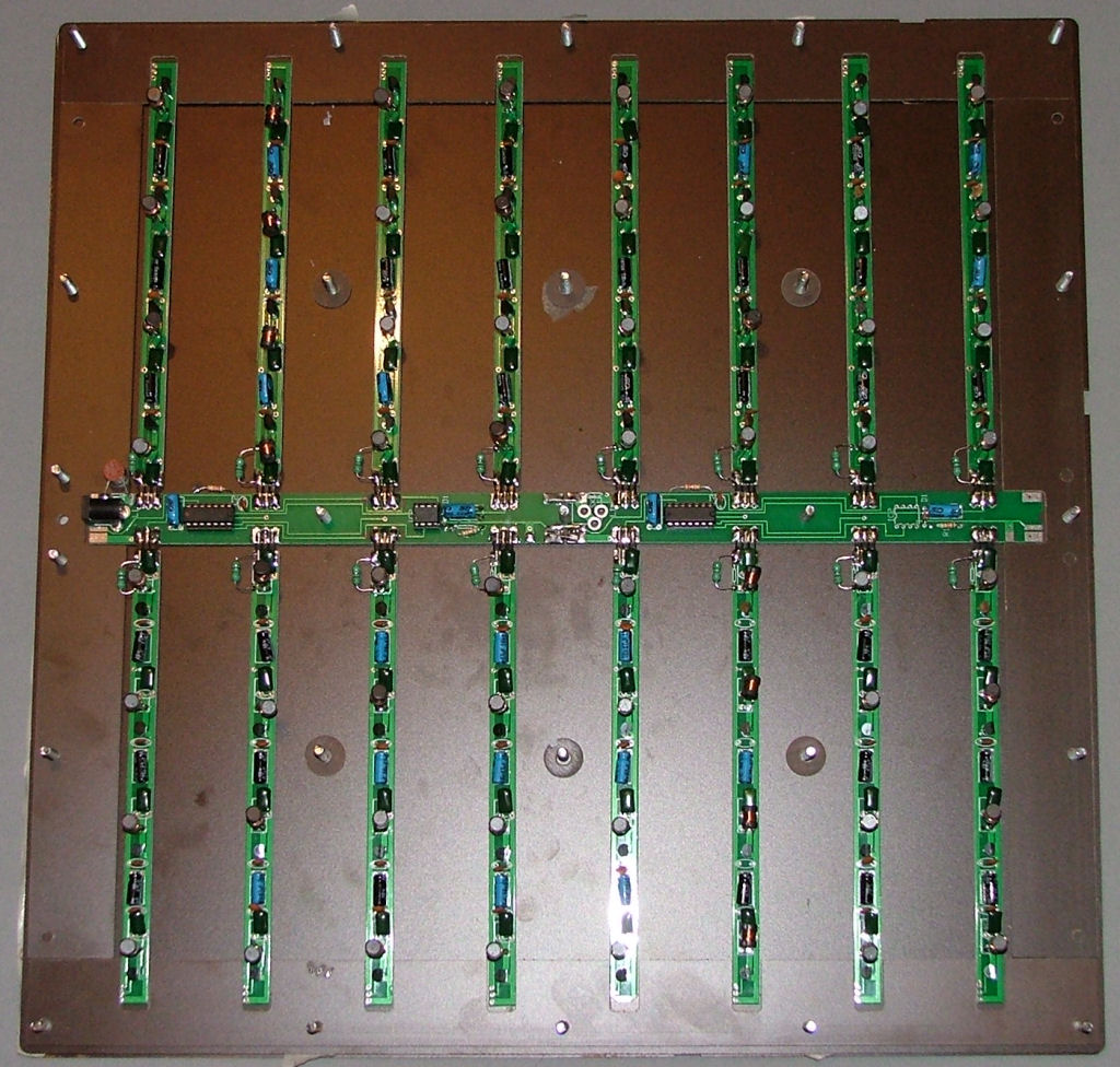
Assembling the complete PCB frame is easier using the board case as a guide. Build up the first 2 layers of the sides and assemble the spine and driver PCBs as shown. The coil PCBs with parts fitted on the top side are at the bottom of the case, the 'mirror' PCBs are at the top.
Centre the header pins on the spine PCB pads and solder in place for all 16 coil PCBs. They'll be tested one at a time as any faults at this stage could destory all the driver transistors that are powered.
With your multimeter on a low ohms range check between the 3 pins on each coil PCB to make sure there aren't any shorts. Reconnect the meter on a low mA range again across F1 and repeat the power up test, the current should still be less than 30mA.
Check the voltages again at the centre pin of each coil driver PCB, it should be about the same as your last test a few posts back. Any missing voltage here will probably be a solder bridge under a transistor.
Re: Board PCBs
It's now time for the final power up testing, with the coil drivers running with a 12V supply one at a time. You'll need a few completed piece PCBs with nixies fitted at this point as well.
Temporarily tag one of the chokes (green resistor-like component) across the L1 pads on the first coil PCB (the order isn't important). The photograph shows a number of them fitted but for now just connect ONE at a time.
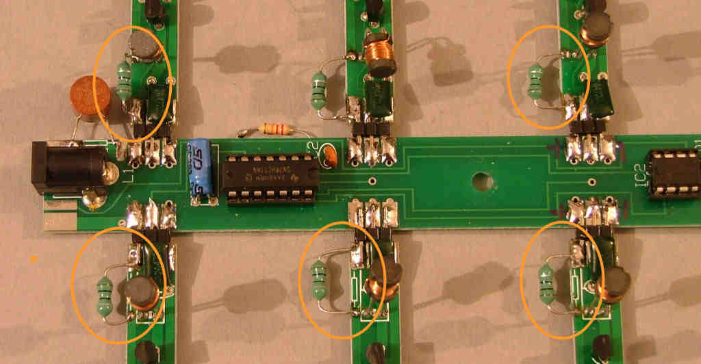
Connect your meter on a mA range that will display up to 250mA to the F1 pads and switch on. You should have a reading of 70-85mA, if it's higher than 100mA switch of quickly and check for shorts under that coil PCB.
If the current reading is OK hold one of the completed piece PCBs with its pickup coil near one of the four powered coils, its nixie should light up. If not try another piece PCB in case there's a fault with that piece.
Once you've confirmed it's working switch off, remove the choke from that PCB, tag it onto the next and repeat the testing process for the next 15. Don't leave a working PCB's L1 connected up once tested as it could be damaged if the next one you try has a fault.
After all 16 have been tested and are working fit chokes on the first 4 boards L1 pads. Repeat the power on test with the mA meter set to a 2A or similar range. You should have a reading of about 300mA. Fit another 4 chokes to the next 4 boards and repeat, the reading should increase by about 300mA each time until you have all 16 connected and a reading of about 1.2Amps. At this stage remove the meter and fit F1.
The electrical assembly and testing is now complete and it's time for the fun job of bending each coil to exactly where the centre of each square will be. (Still less fun than winding 96 coils by hand )
Whilst the small coil size of this design makes the coil position and piece placement more critical it does allow metallic items to be used near them, which was impossible with the older designs. The first modification I'm working on will be a wall-mounted vertical board with the pieces held in place using an array of magnets. Metal powder filled resin piece cases are also now possible for a real copper/brass/iron finish.