Page 1 of 3
3 - Clock PCB assembly
Posted: Thu Oct 15, 2015 4:24 pm
by Tony
Please read through these BEFORE starting on construction.
Re: Clock PCB assembly
Posted: Mon Oct 19, 2015 3:07 am
by Tony
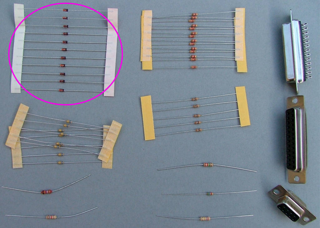
Fit the 11x 1N4148 diodes in locations marked for D1,2,3,4,5,6,7,8,9,10 and 11 as shown: **NOTE** the band marked on the end of the diode body must face the same way as shown in the photograph, this is also indicated on the PCB with a thick white band.

Re: Clock PCB assembly
Posted: Mon Oct 19, 2015 3:10 am
by Tony
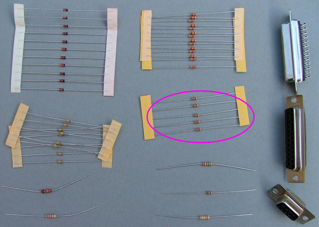
Fit the 5x 100r resistors (brown-black-brown) or 91R (white brown black) in locations marked for R1,2,6,7 and 10 as shown:

Re: Clock PCB assembly
Posted: Mon Oct 19, 2015 3:13 am
by Tony
Fit the 2x 1K2 resistors (brown-red-red) or 1k (brown-black-red) in locations marked for R4 and R11 as shown (ignore R12, it isn't used now):


Re: Clock PCB assembly
Posted: Mon Oct 19, 2015 3:14 am
by Tony
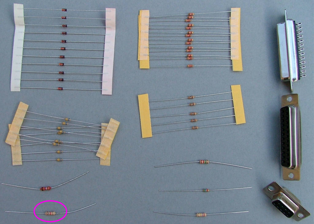
Fit the 1k8 resistor (brown-grey-red) or 2k2 (red red red) in the location marked for R3 as shown:

Re: Clock PCB assembly
Posted: Mon Oct 19, 2015 3:15 am
by Tony
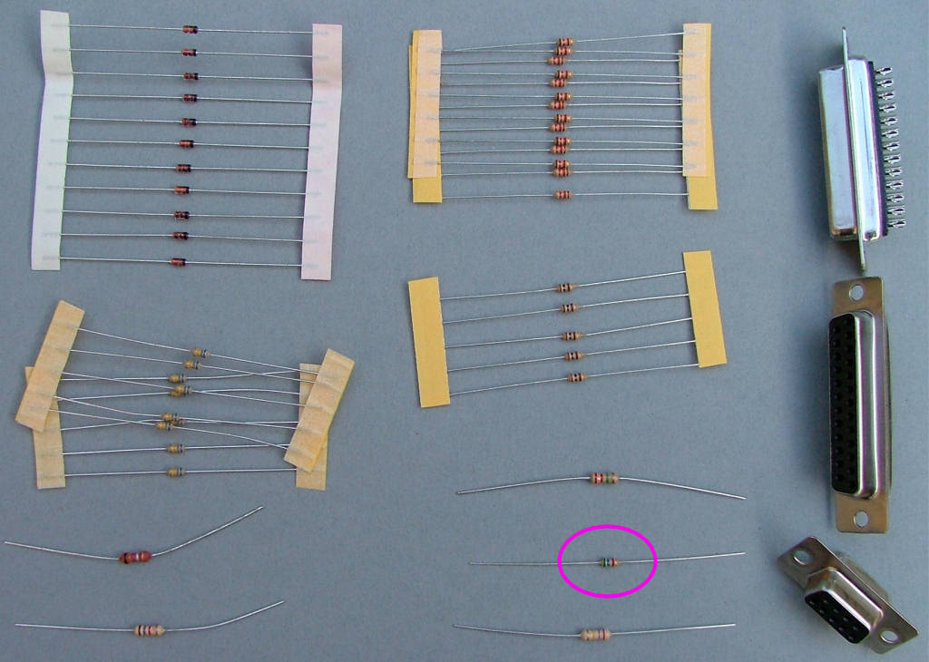
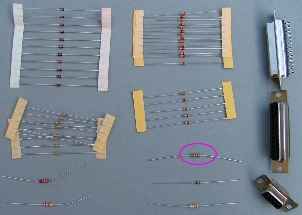
Fit the 5K6 resistor (green-blue-red) in the location marked for R5 as shown:

Re: Clock PCB assembly
Posted: Mon Oct 19, 2015 3:17 am
by Tony
Fit the 2M2 resistor (red-red-green) in the location marked for R9 as shown, this one is a bit tight:

Re: Clock PCB assembly
Posted: Mon Oct 19, 2015 3:19 am
by Tony
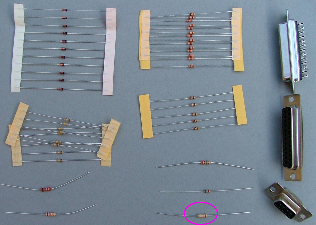
Fit the 270k (Red violet yellow) in the location for R13 just above T11 as shown:

Re: Clock PCB assembly
Posted: Mon Oct 19, 2015 3:41 am
by Tony
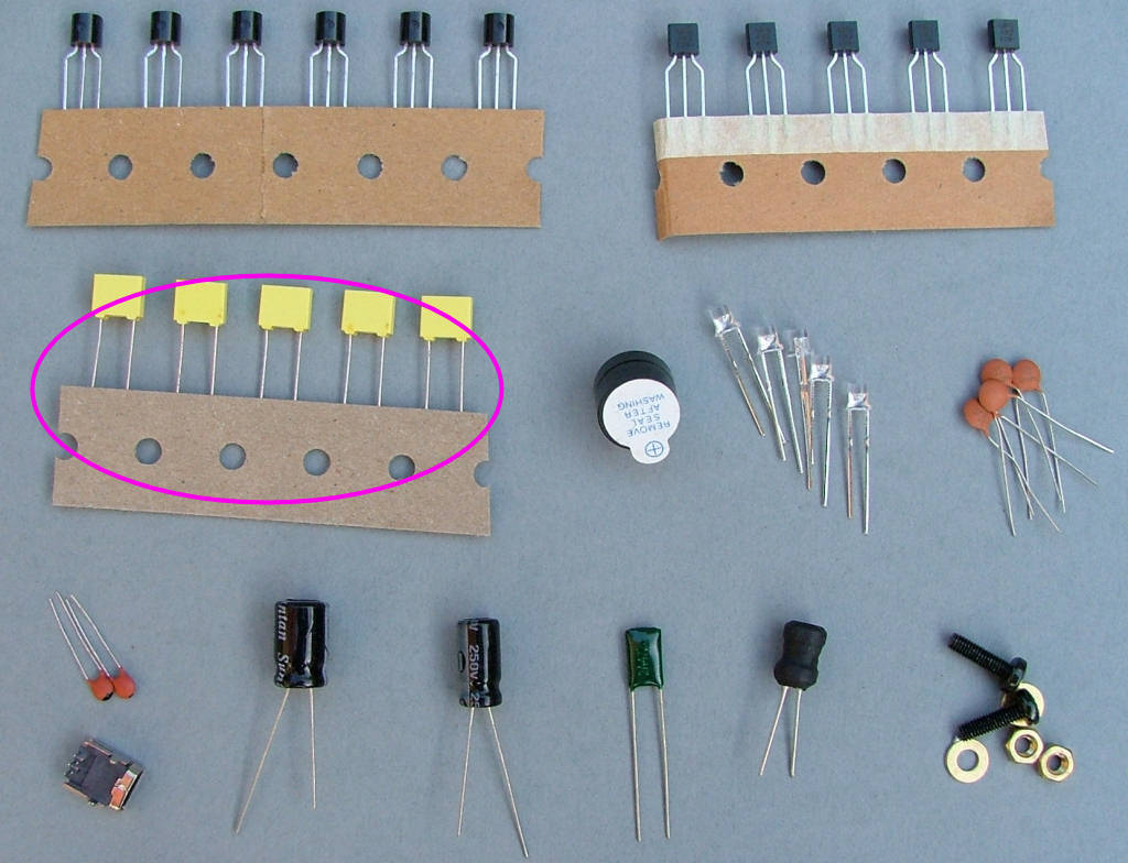
Fit the yellow plastic .22u capacitors x5 in locations marked for C12,13,14,15 and 16 as shown:

Re: Clock PCB assembly
Posted: Mon Oct 19, 2015 3:42 am
by Tony
Fit the brown 10n (marked 103) or 33n (marked 333) ceramic capacitors x3 in locations marked for C1,4 and 11 as shown:
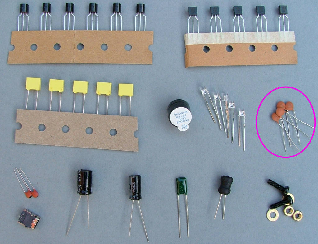

Ignore C6 as it is no longer required on the later PCBs.


