Powering up the complete parts
Posted: Sat Sep 15, 2012 10:39 pm
NOTE: This information only applies to the first 20 kits supplied with plain copper engraved PCBs not the later etched boards and is left here for those who may not yet have started on the old kits.
----------------------------------------------------------------------------------------------------------------------------------------
When you receive the kit there should be one completed display PCB and one board PCB with enough parts fitted to power up one coil.
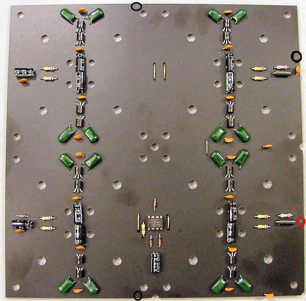
Connect it to a 12V supply, preferably through a milliammeter to the points marked in this picture, + to either of the red circled holes and - to either of the black circled holes. You only need to connect to one of each.
When powered up you should have a reading of about 24-26mA. if it's about 6mA one end of the coil may have worked loose, tighten up the nuts a little and try again. if it's over 30mA check for shorts or lumps of metal nearby.
Plug one of the IN7 nixies into the display PCB and put it on top of the powered base PCB coil. The current reading should now be about 40mA and it should display a 'm'. You will notice the display is brighter if held slightly above the coil - this is due to the coil being designed for the top board to be in between them.
At this point it's probably worth building the display PCBs first and testing them all against this one coil, if you've missed any turns when winding them it will show up in a higher/lower than average current reading.
