Page 1 of 1
4 - PCB assembly - Nixies
Posted: Mon Oct 19, 2015 4:36 am
by Tony
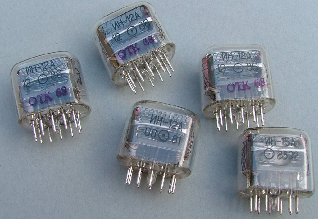
Repeat the power up test again, this time the current reading should be about 20-25mA and the 5 blue LEDs will light up, flickering slightly. the 4 amber LEDs should be flashing to indicate the time needs to be set. If we're this far it's now time to fit the nixies into their sockets. You'll notice one of the pins internally has white insulating paste on it, this is the anode and faces to the bottom right of the sockets. Fit 2x IN12 to the leftmost 2 sockets, then the IN15 in the centre followed by the other 2x IN12 on the right.
Re: PCB assembly - Nixies
Posted: Mon Oct 19, 2015 4:37 am
by Tony
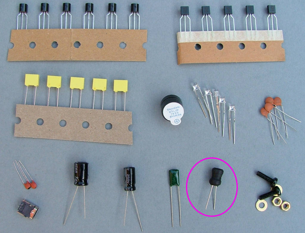
Nearly time for another power test: Fit the 20uH coil (copper wire spool) into the position marked Coil L1.

This is probably a good time to mention from this point, DO NOT TOUCH the board whilst powered and allow 30-60 seconds after switching off before handling it, it's generating 180V+. It's at a low current it will still bite and could be dangerous in the wrong circumstances (Note the wrong circumstances are probably when you'll touch it). There is a discharge resistor but it takes a few seconds after power is removed to empty the 200V capacitor.
Connect the mA meter again to the space marked for R8/removed solder resist. Connect the USB power supply and switch on, watching the meter. This time if everything is working the current should be between 200-250mA and the blue LEDs and nixies will light up - if not switch off quickly and recheck everything, mostly around T12,C10 and the resistors/transistors behind the nixies.
If everything went OK you should now have a display similar to 00+00 with flashing decimal points and a colon cycling between + and -.
Re: PCB assembly - Nixies
Posted: Mon Oct 19, 2015 4:42 am
by Tony
Fit the resettable 'polyfuse' which looks like a caramel covered capacitor in the place marked R8.
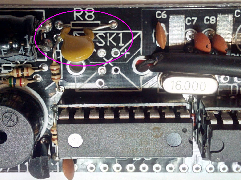
Connect the USB power supply and leave it run for a while.
Re: PCB assembly - Nixies
Posted: Mon Oct 19, 2015 6:10 pm
by Tony
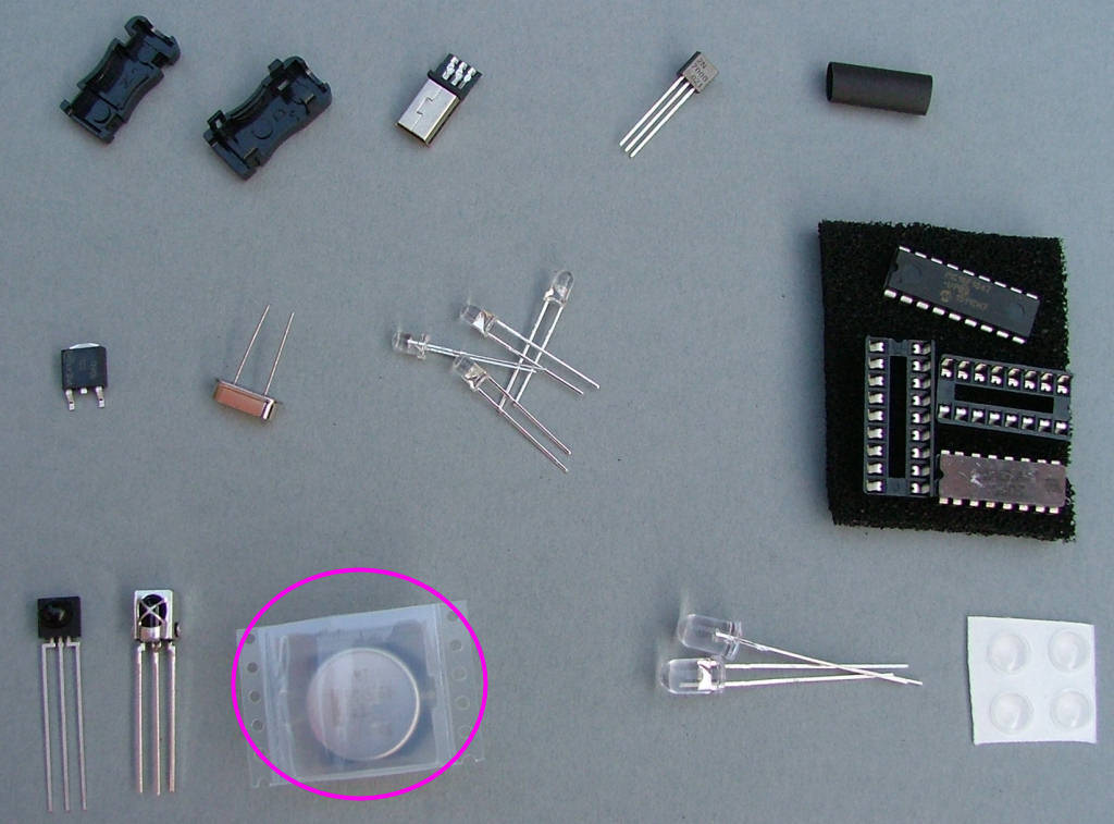
The final component is the memory backup capacitor. Power down the clock and wait about a minute. Take the 0.47F capacitor out of its packing and bend the pins so they're pointing down, at 90 degrees to the base, ready to insert into the PCB. FIt it into the place marked C2, the band on the case top is the negative and faces the front (down).
Later kits may be supplied with a smaller black plastic covered capacitor with tabs that are soldered onto the PCB pads directly or a blue Aerogel 0.47F capacitor.

Re: PCB assembly - Nixies
Posted: Mon Oct 19, 2015 6:36 pm
by Tony
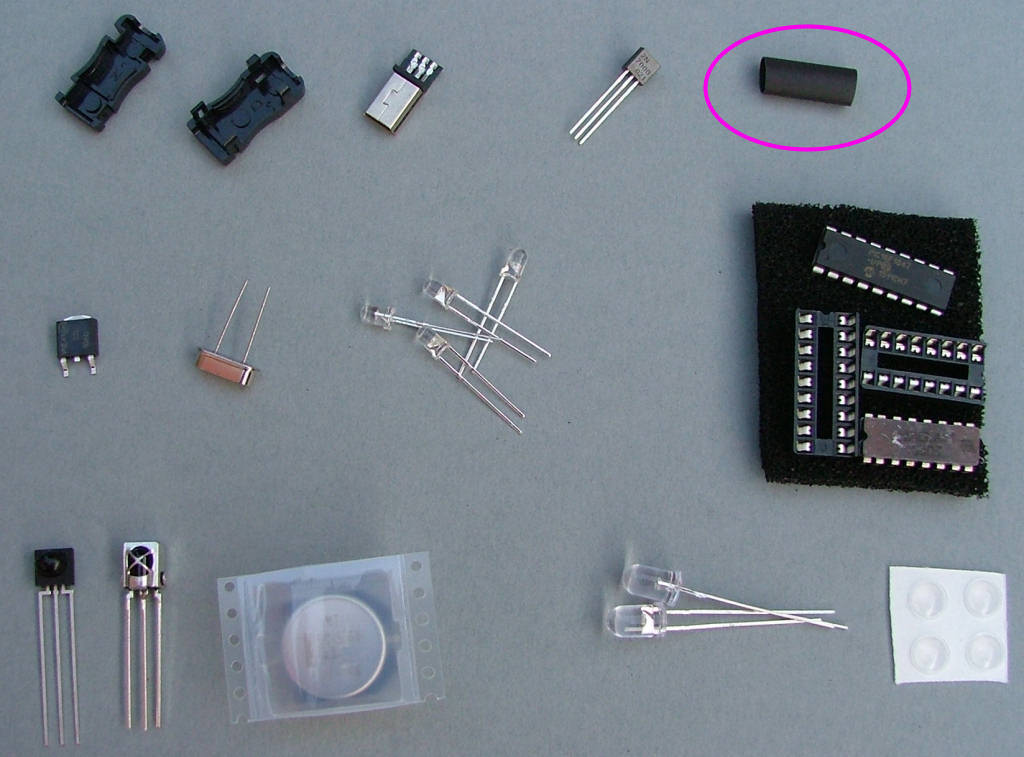
Before building it into the case, cut a piece of heatshrink sleeving about 1/2" long and slip it over the IR LED LED8. This prevents unwanted IR reaching the detector IC4. Shrink it a little around the LED to stop it slipping off but don't make it too thin..
