3 - Coil Assembly
Posted: Fri Dec 01, 2017 6:36 am
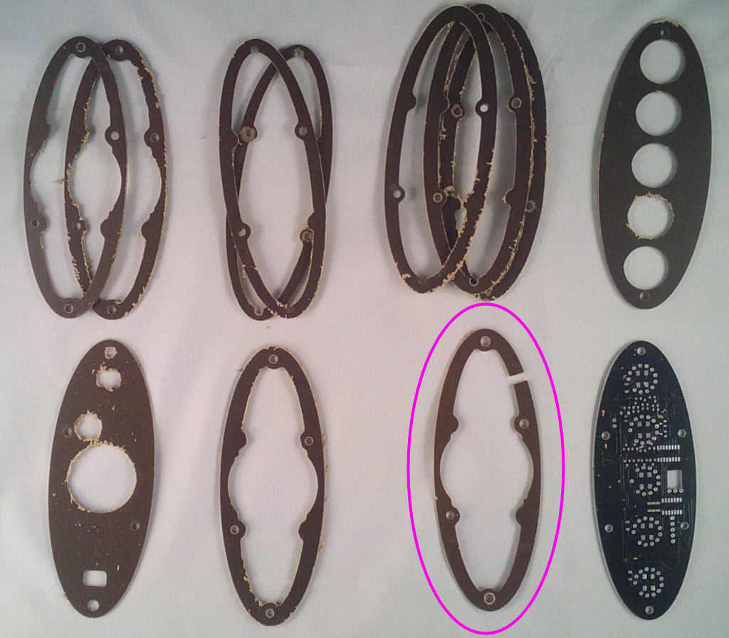
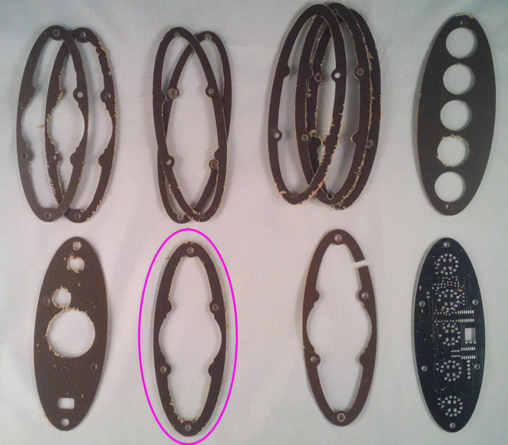
Unpack the case piece bag and separate the laminate parts for sanding. Spending some time here wet sanding with fine emery paper will give a *much* smoother rounded finish and if you're really patient the bakelite top can be polished to a gloss finish with a fine polishing paste such as car paint restorer.
Carefully sand the case top and bottom panels making sure not to scratch them, the side rings will be hidden so scratches aren't so much of a problem but they are fragile so don't put too much pressure on them.
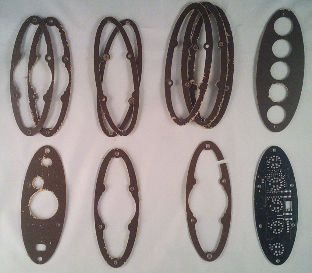
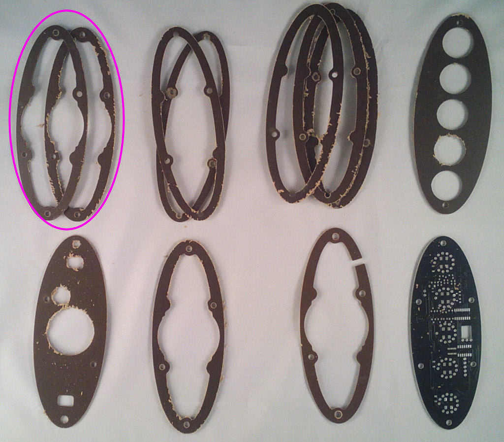
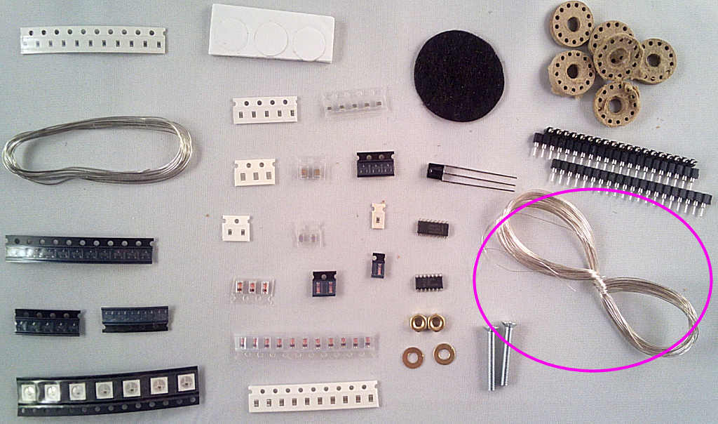
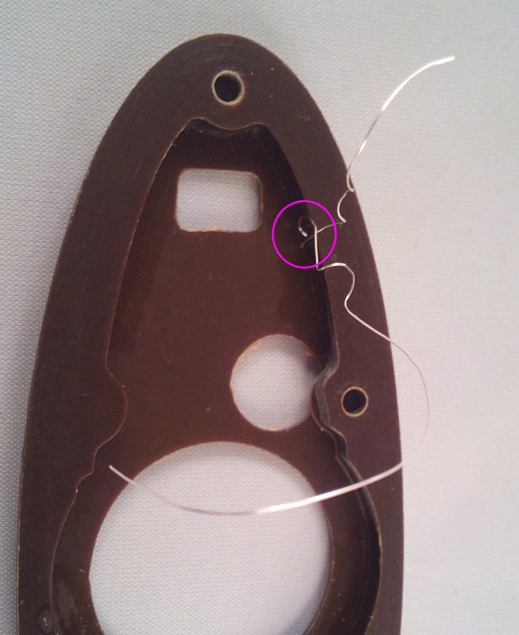
The coil consists of a former made using a stack of four paxolin laminate pieces. The coil itself is wound from 0.2mm silver plated copper wire, enamelled with a clear lacquer for insulation. You'll need to make this to test the clock PCB and before moving onto the case assembly instructions.
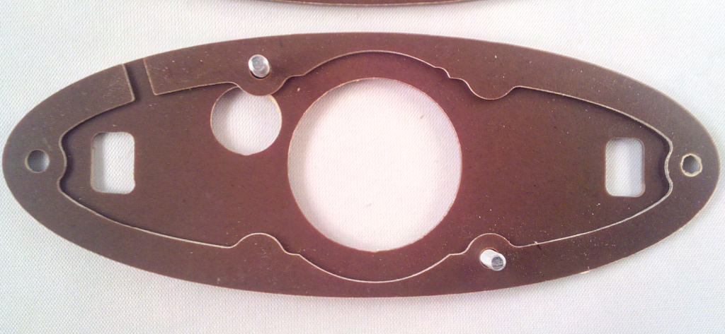
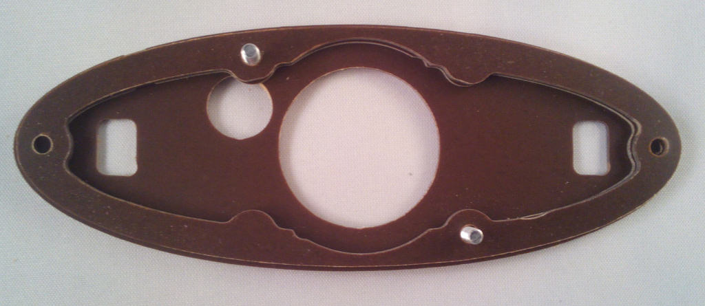
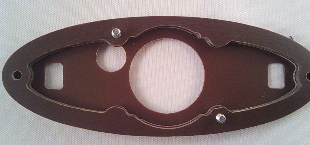
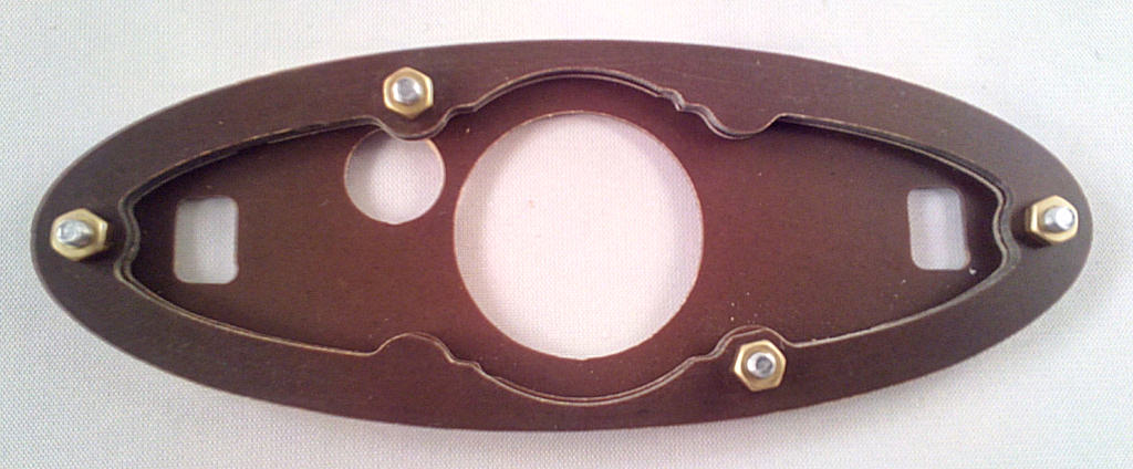
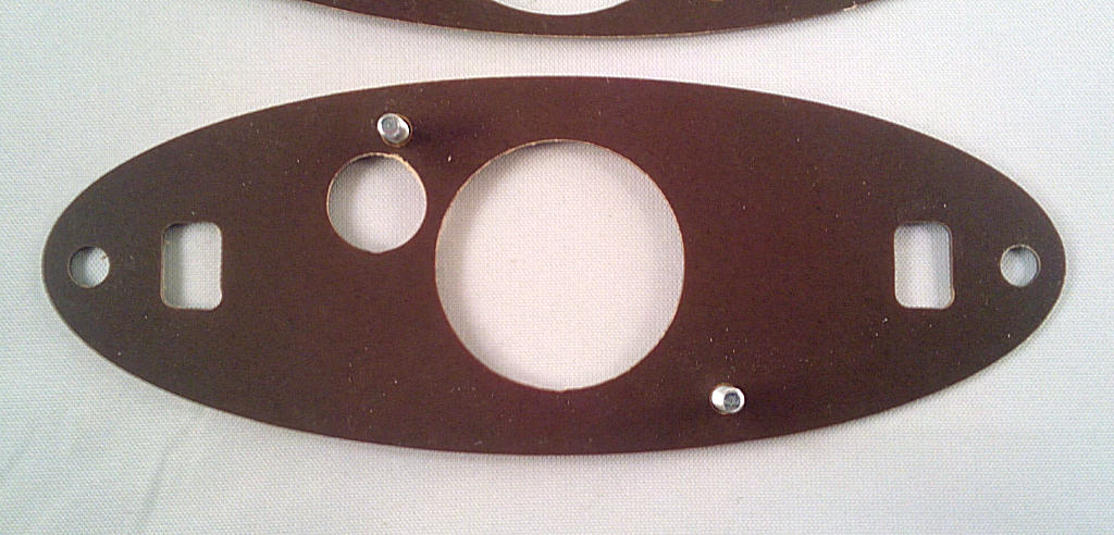
Start with the case base panel and insert the 2x M3 bolts into the holes at each side. Make sure the holes in the panel face the way shown in the pictues.
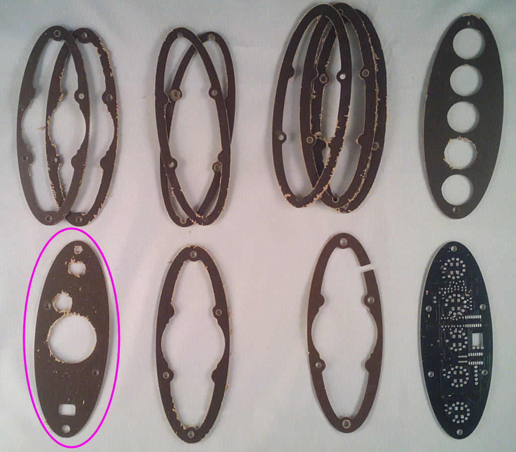
Carefully sand the case top and bottom panels making sure not to scratch them, the side rings will be hidden so scratches aren't so much of a problem but they are fragile so don't put too much pressure on them.

The coil consists of a former made using a stack of four paxolin laminate pieces. The coil itself is wound from 0.2mm silver plated copper wire, enamelled with a clear lacquer for insulation. You'll need to make this to test the clock PCB and before moving onto the case assembly instructions.
Start with the case base panel and insert the 2x M3 bolts into the holes at each side. Make sure the holes in the panel face the way shown in the pictues.


