Page 1 of 2
4 - Case Assembly
Posted: Sat Dec 02, 2017 3:23 am
by Tony
The exact finish will depend on your own preference and the amount of work you want to do. The steel base can be blacked or copper plated though the relay kits are supplied with silver plated wire to match the bare steel. The paxolin strips can be sanded, polished and oiled to give a satin or sem-gloss finish.
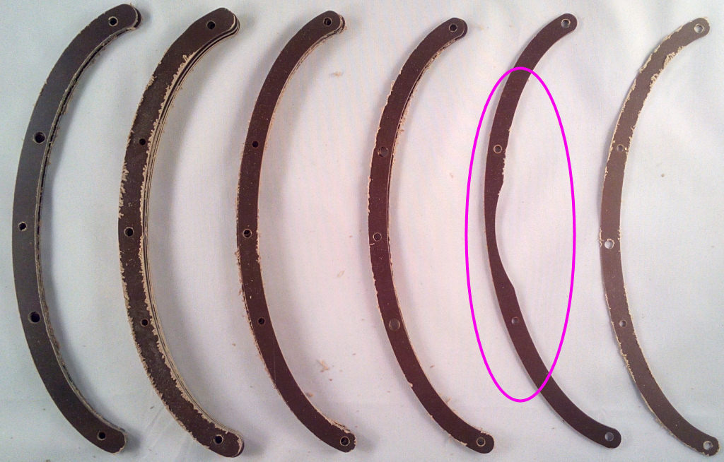
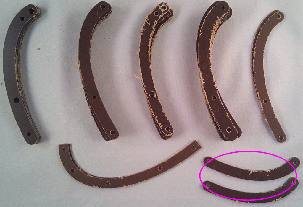
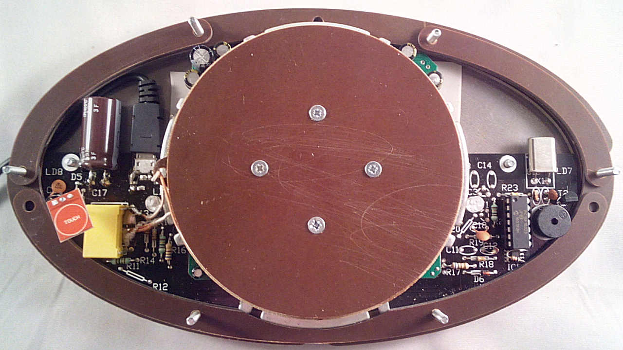
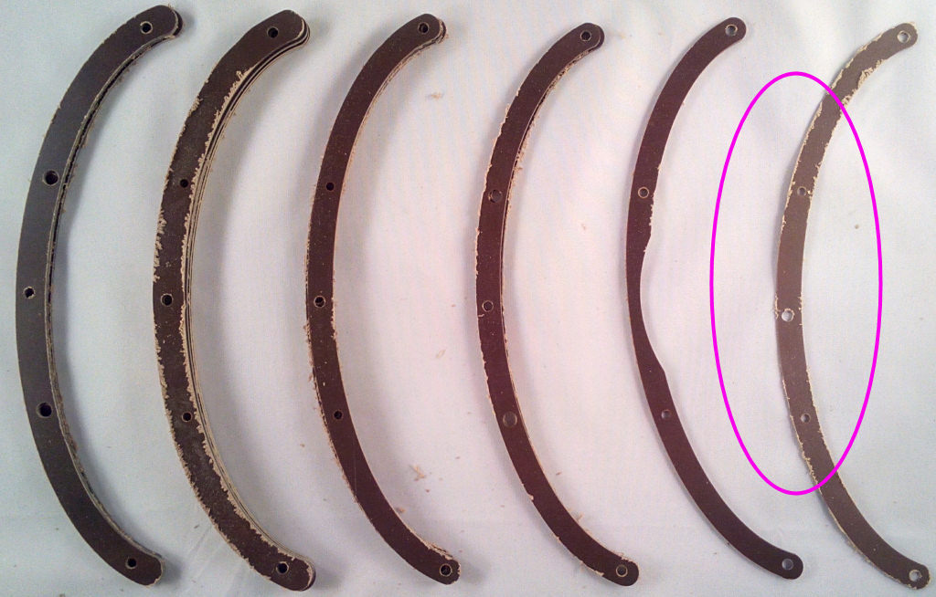
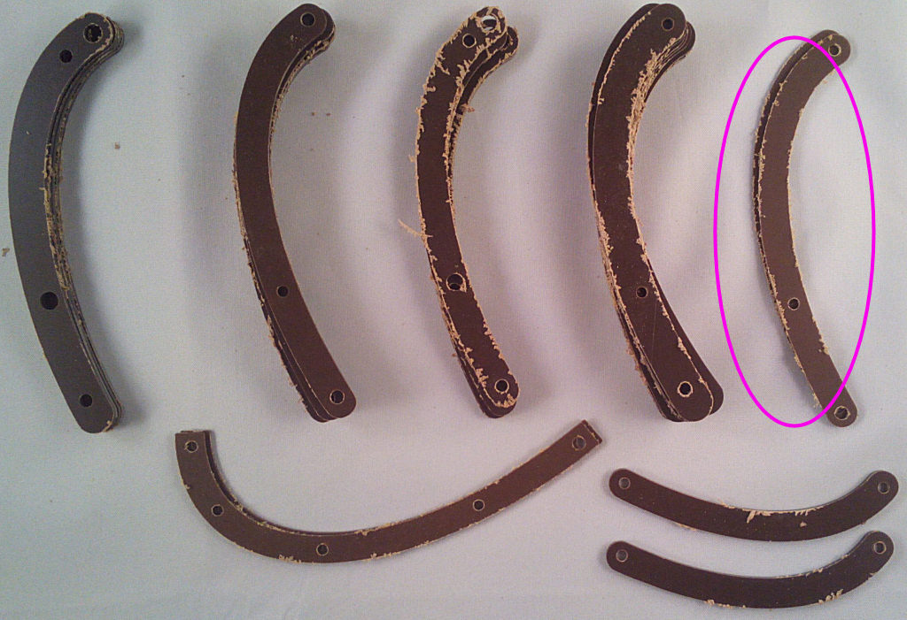
Before starting, make sure the touch switch is just below the level of the lid (the top of the coil former disc) - it doesn't need to be flat, just point the tip of it up and it should work. Some of the wide long strips have misplaced holes so you may need to correct them before assembly with a file or dremel.
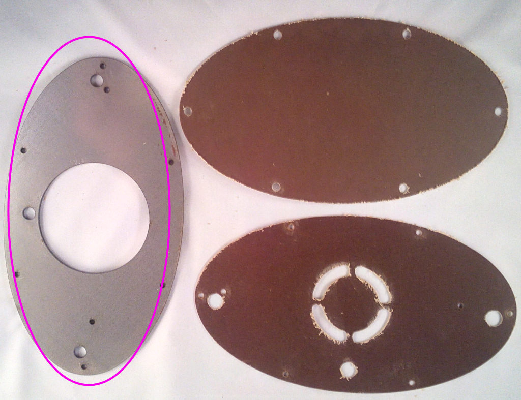
Put the paxolin base cover on the steel baseplate exactly as shown here - make sure the holes line up as in the picture or it'll be upside down.
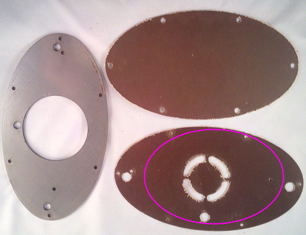
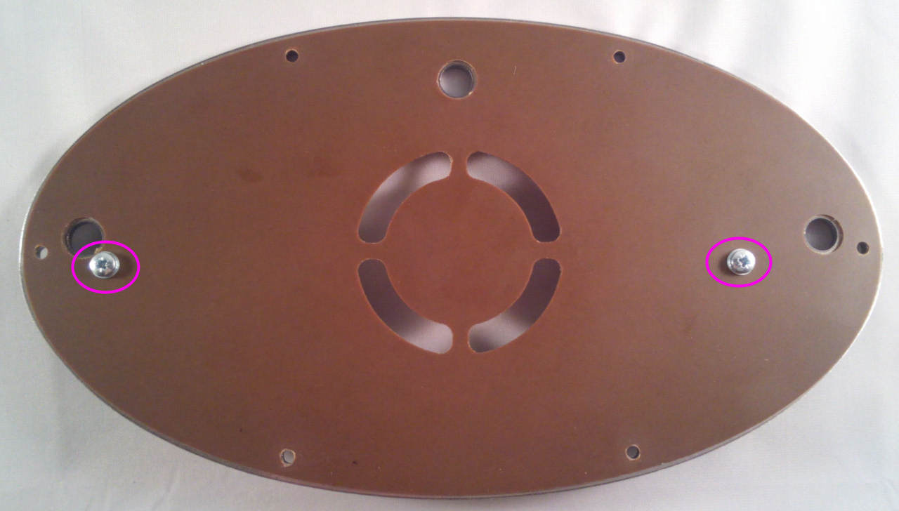
Put the 2 short M3 bolts through the holes marked:
Re: 4 - Case Assembly
Posted: Mon Jan 08, 2018 4:25 am
by Tony
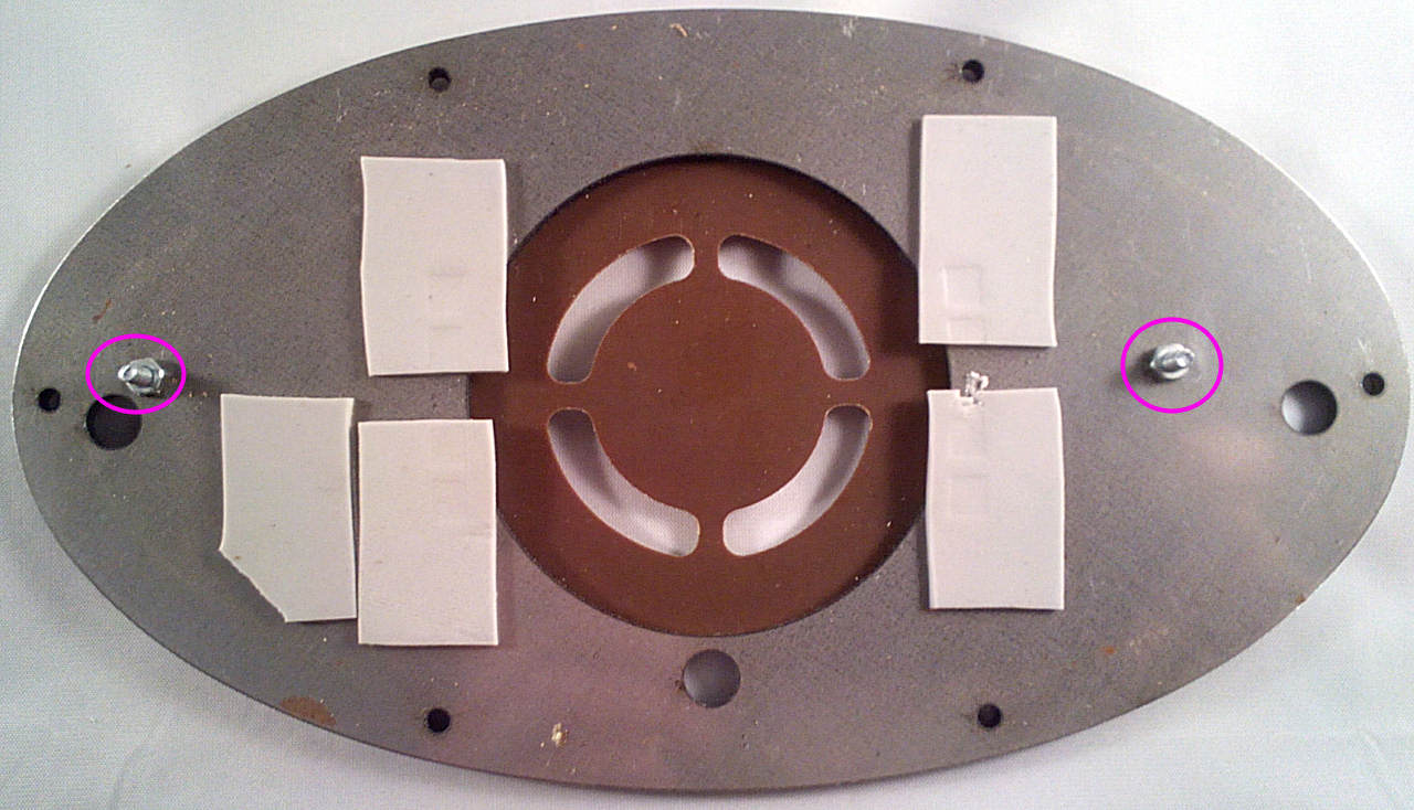
Turn it over and fit nuts onto the bolts to hold them in place:
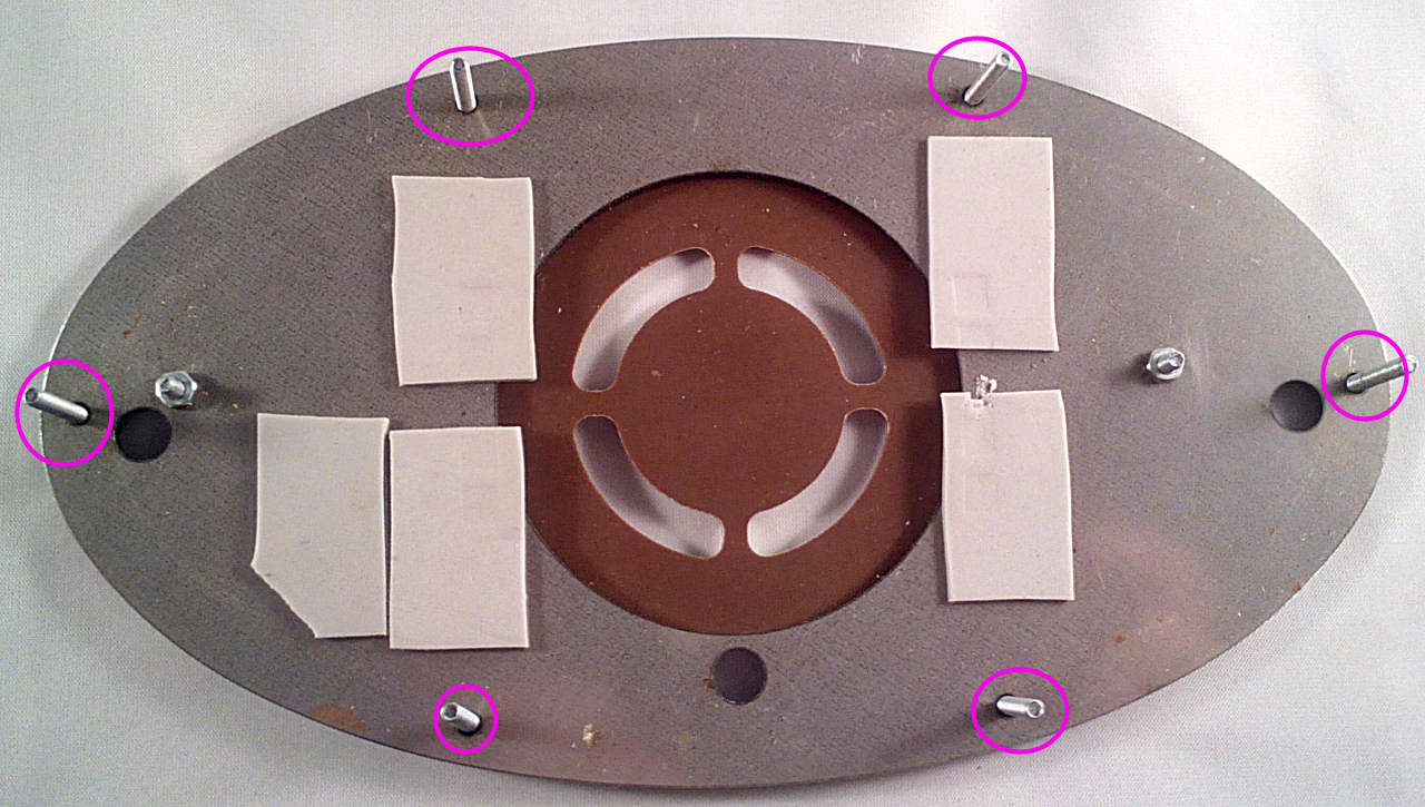
Put the 6x long M3 bolts through the outer holes - don't use washers as they're only just long enough:
Re: 4 - Case Assembly
Posted: Mon Jan 08, 2018 4:26 am
by Tony
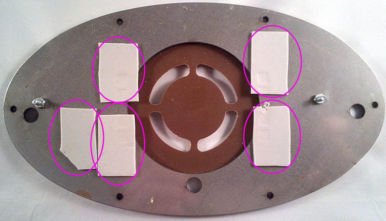
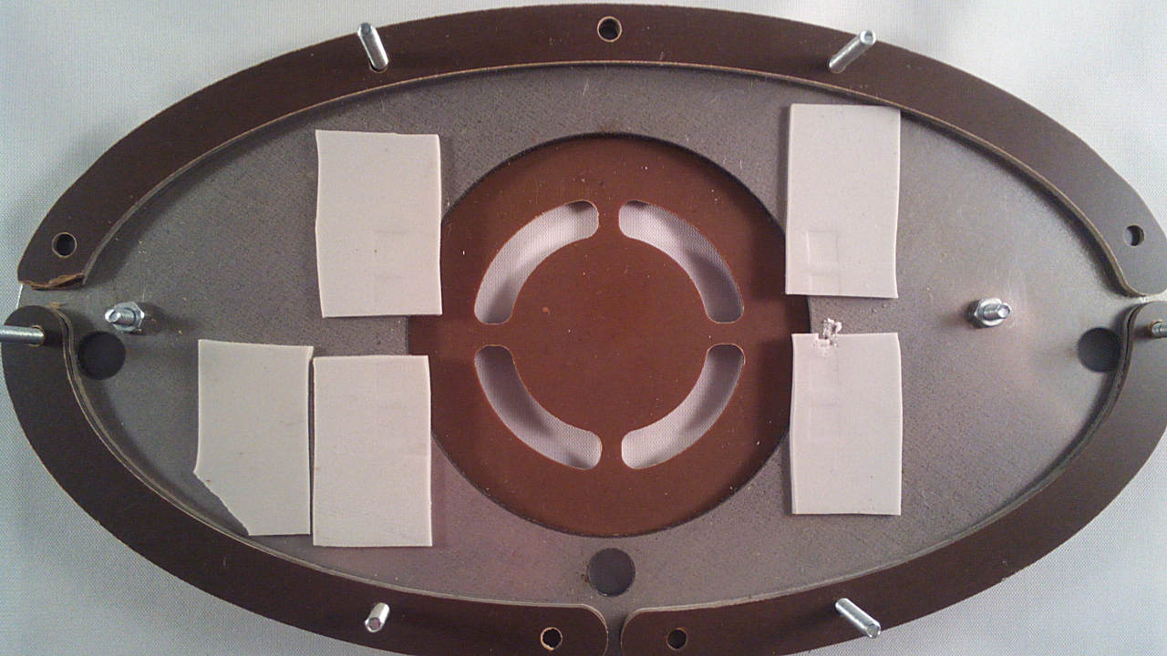
Cut some pieces of silicone heatsink pad (from Bag1) and lay them on the baseplate as shown:
Re: 4 - Case Assembly
Posted: Mon Jan 08, 2018 4:30 am
by Tony
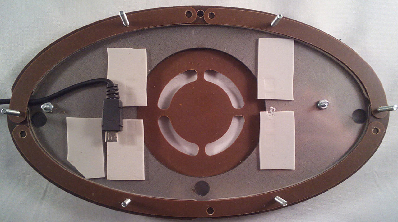
Next you'll need 1x long narrow strip with 3mm holes and 2x short narrow strips with 3mm holes:
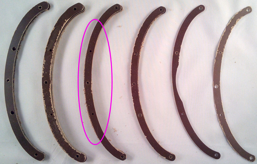
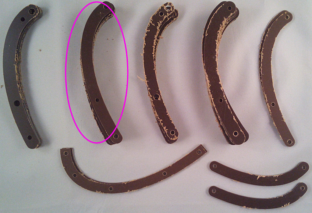
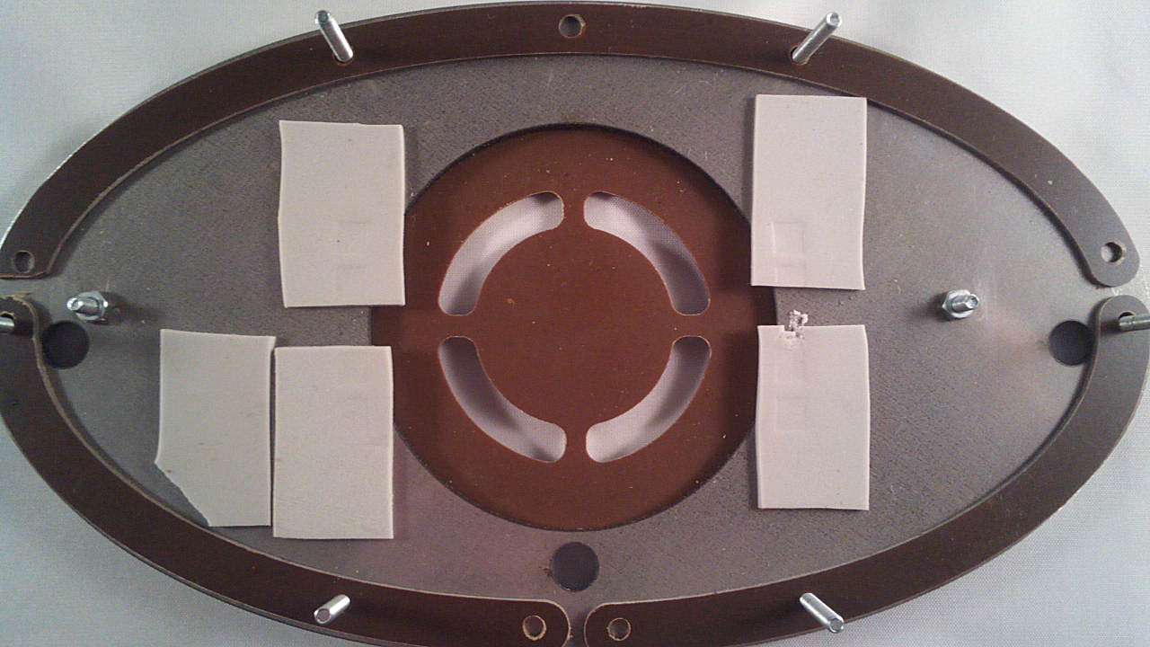
Note the end of the strips on the left have been trimmed slightly to allow the USB cable to fit.
Re: 4 - Case Assembly
Posted: Mon Jan 08, 2018 4:31 am
by Tony
Then a layer of 1x long wide strip with 3mm holes and 2x short wide strips with 3mm holes:
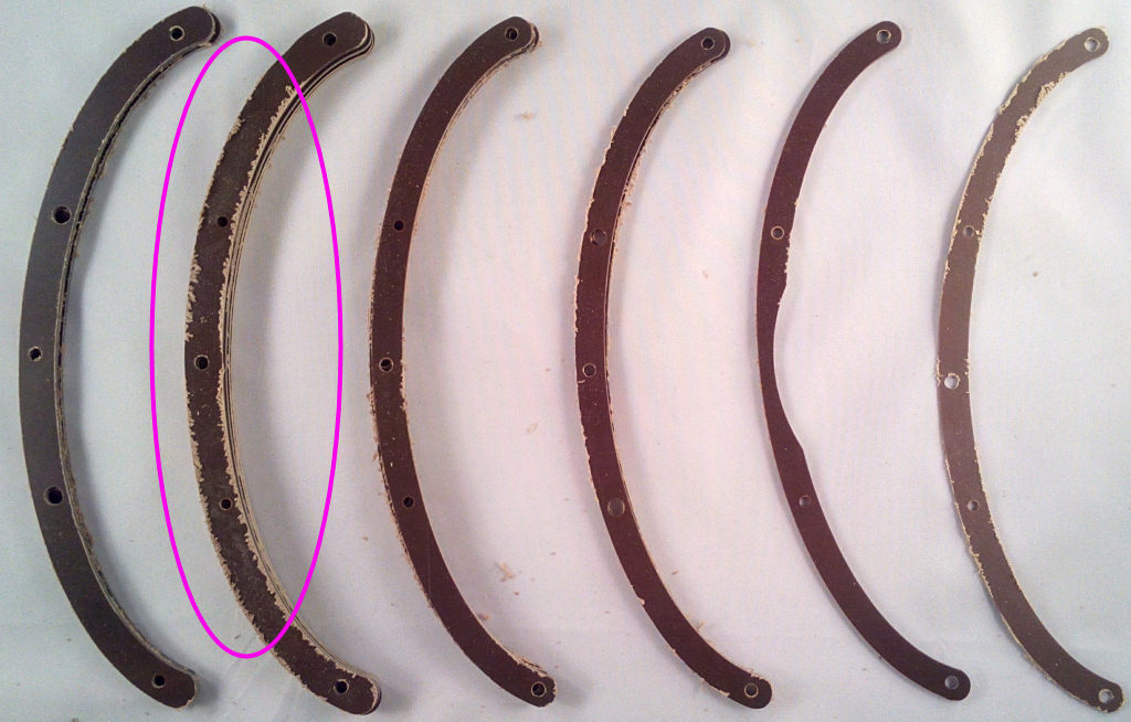
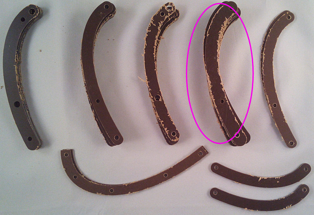
Note the end of the strips on the left have again been trimmed slightly to allow the USB cable to fit.
Re: 4 - Case Assembly
Posted: Mon Jan 08, 2018 4:33 am
by Tony
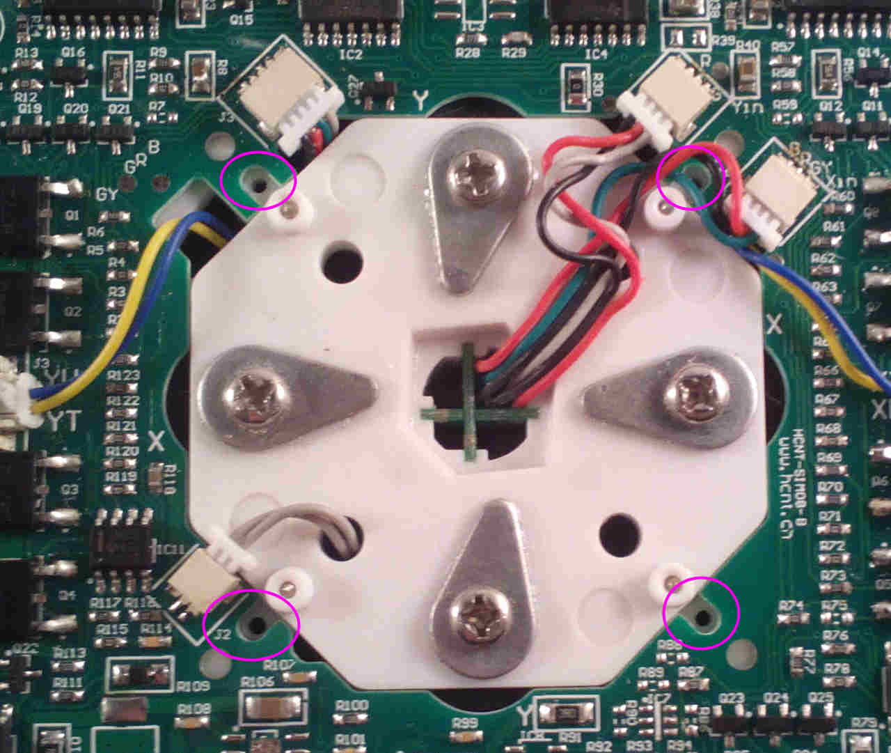
Remove the 4x small screws that hold the levitation PCB to the magnet frame. This will prevent stress on the PCB when it's held by the case strips.
Re: 4 - Case Assembly
Posted: Mon Jan 08, 2018 4:34 am
by Tony
Feed the USB cable through the gap on the left and build another layer as shown.
You'll need the 0.8mm pcb shims for this - 1x long narrow strip with 3mm holes and 2x short narrow strips with 3mm holes:
Re: 4 - Case Assembly
Posted: Mon Jan 08, 2018 4:39 am
by Tony
Drop the levitation PCB assembly over the short bolts and onto the strips as shown. Carefully connect the USB lead.
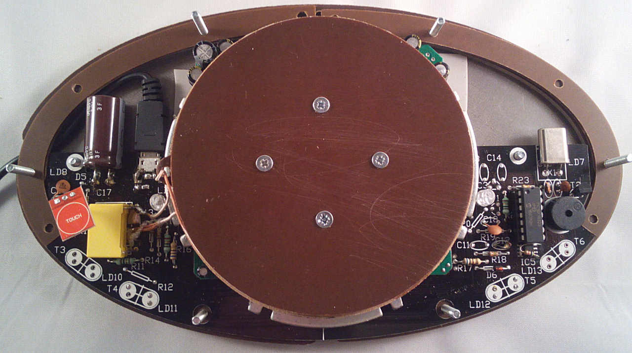
Fit the 2x 0.8mm PCB supports aroud the top of the case:
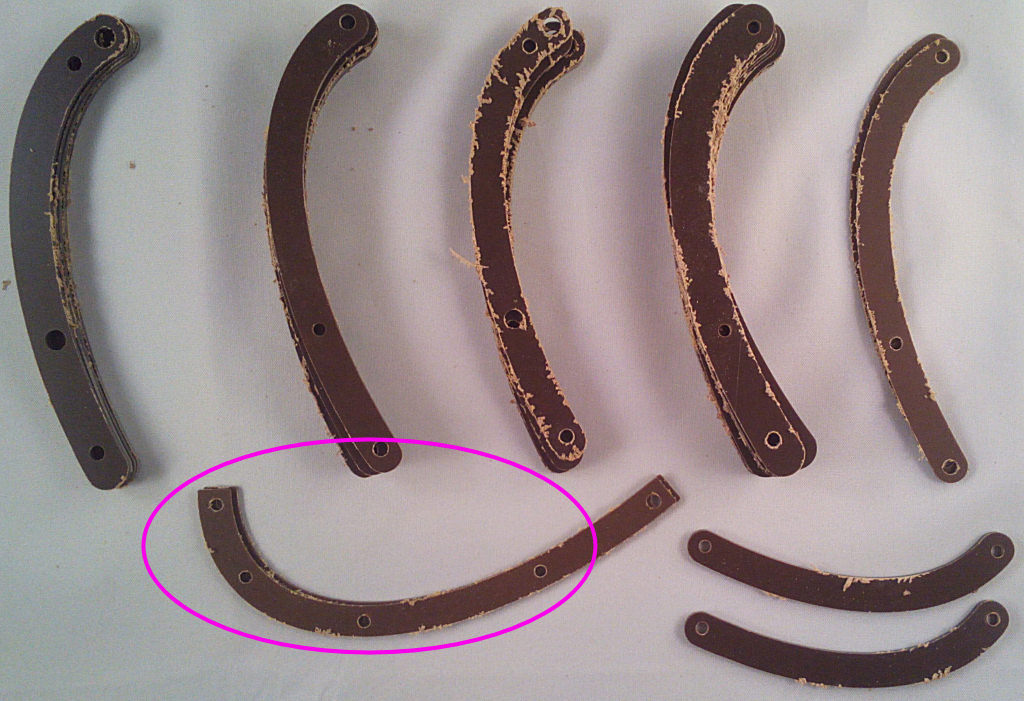
Using 2x washers and bolts, bolt down the PCB.
Re: 4 - Case Assembly
Posted: Mon Jan 08, 2018 4:47 am
by Tony
Now build a layer of 1x long wide strip with 3mm holes and 2x short wide strips with 3mm holes:


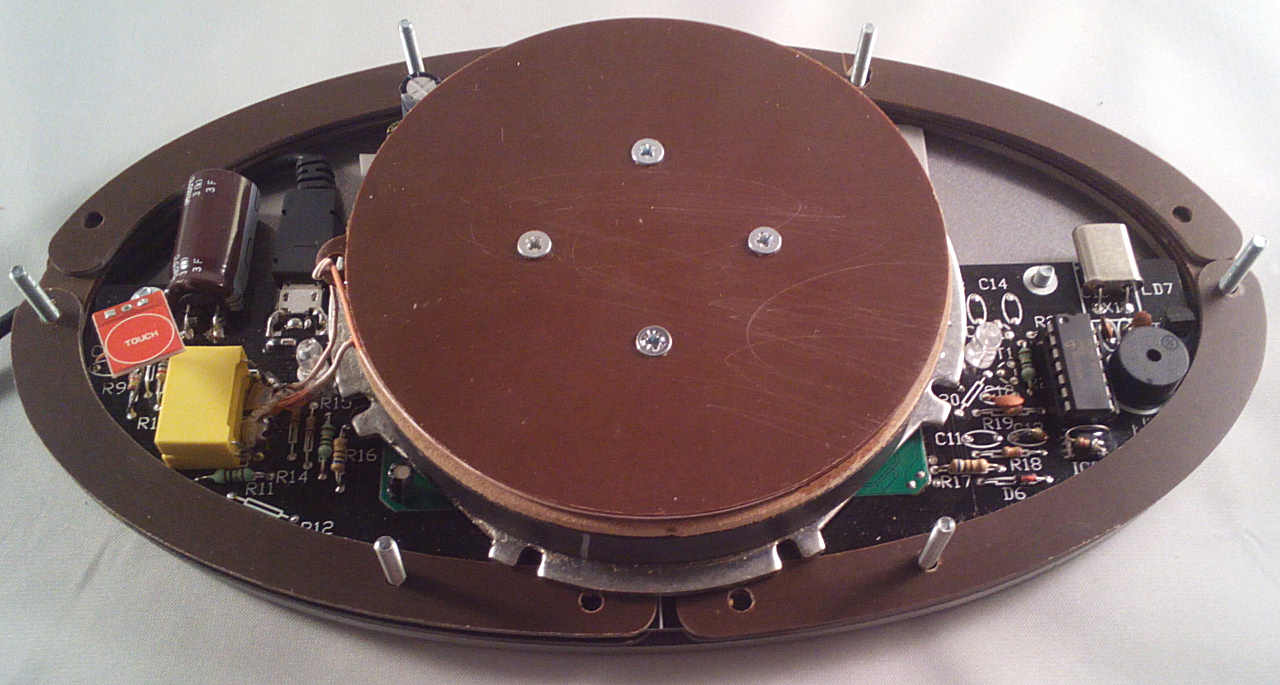
Note you'll need to carefully lift the magnet assembly to fit the strips under it.
Re: 4 - Case Assembly
Posted: Mon Jan 08, 2018 4:49 am
by Tony


