First of all I should mention there are now 2 versions, one using the IR proximity sensor and one using two touchswitches for control. If you have a Bag1 labelled 'CLK501B' and your Bag2 contains 2 small red PCBs then you have the touchswitch version. They are almost identical but to avoid confusion it has its' own assembly threads prefixed 'BUTTON'.
The exact order of assembly will depend on the preference of the builder but convention is to fit the resistors/diodes first followed by capacitors, transistors and ICs in that order.
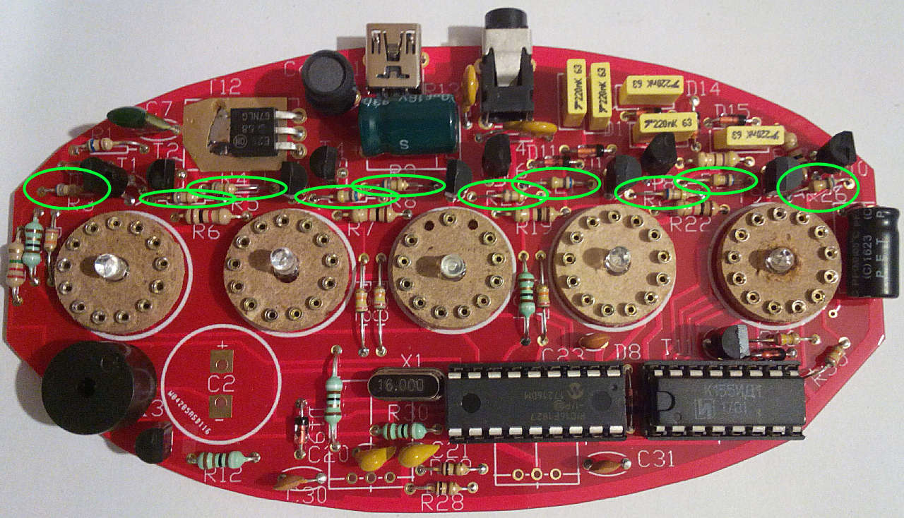
After preparing a suitable working space take the PCB and start with resistors R3,4,5,8,9,20,21,23,24 and 26. These will be 680k, (blue-grey-yellow) or 2m2 (red red green). Fit these in locations marked for R3,4,5,8,9,20,21,23,24 and 26 as shown:
1- BUTTON version PCB assembly - Bag1
Re: BUTTON version PCB assembly - Bag1
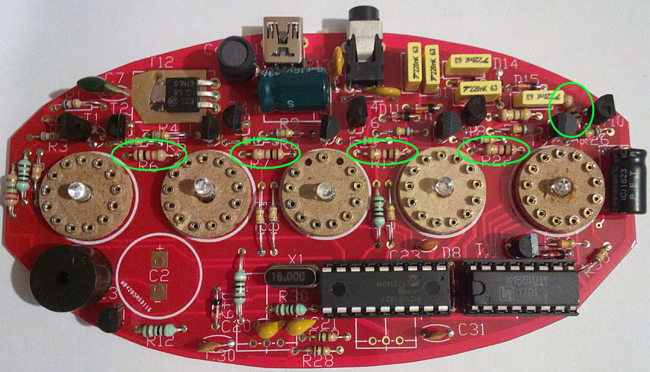
Fit the 5x 1K or 1K2 resistors (brown black red) or (brown-red-red) in locations marked for R6,7,17,19 and 22 as shown:
Re: BUTTON version PCB assembly - Bag1
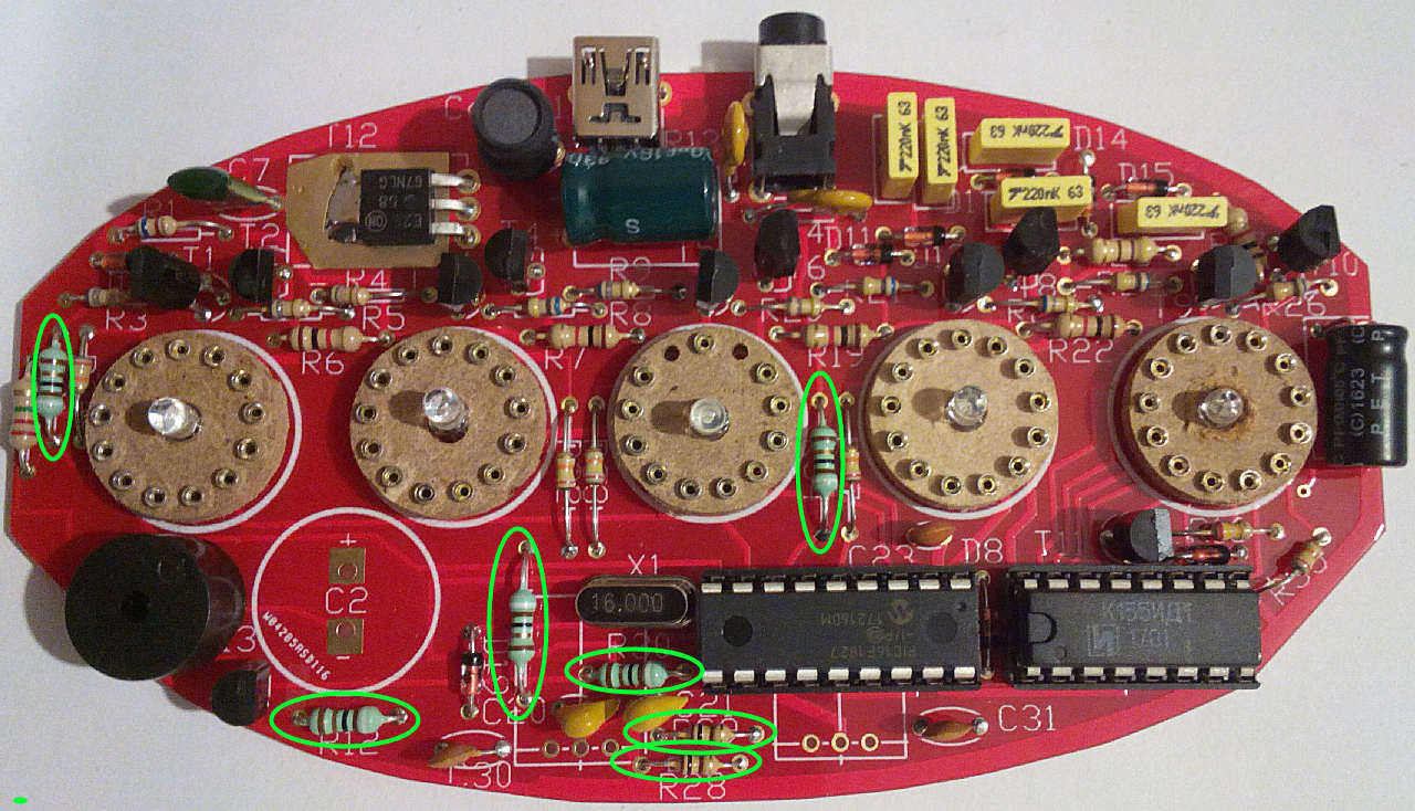
V2: Fit the 7x 100r resistors (brown-black-brown or brown-black-black-black) or 7x 91r resistors (white brown black) - you may receive a mixture of the 2 - in locations marked for R12,28,29,30,30a,31 and 34 as shown:
Re: BUTTON version PCB assembly - Bag1
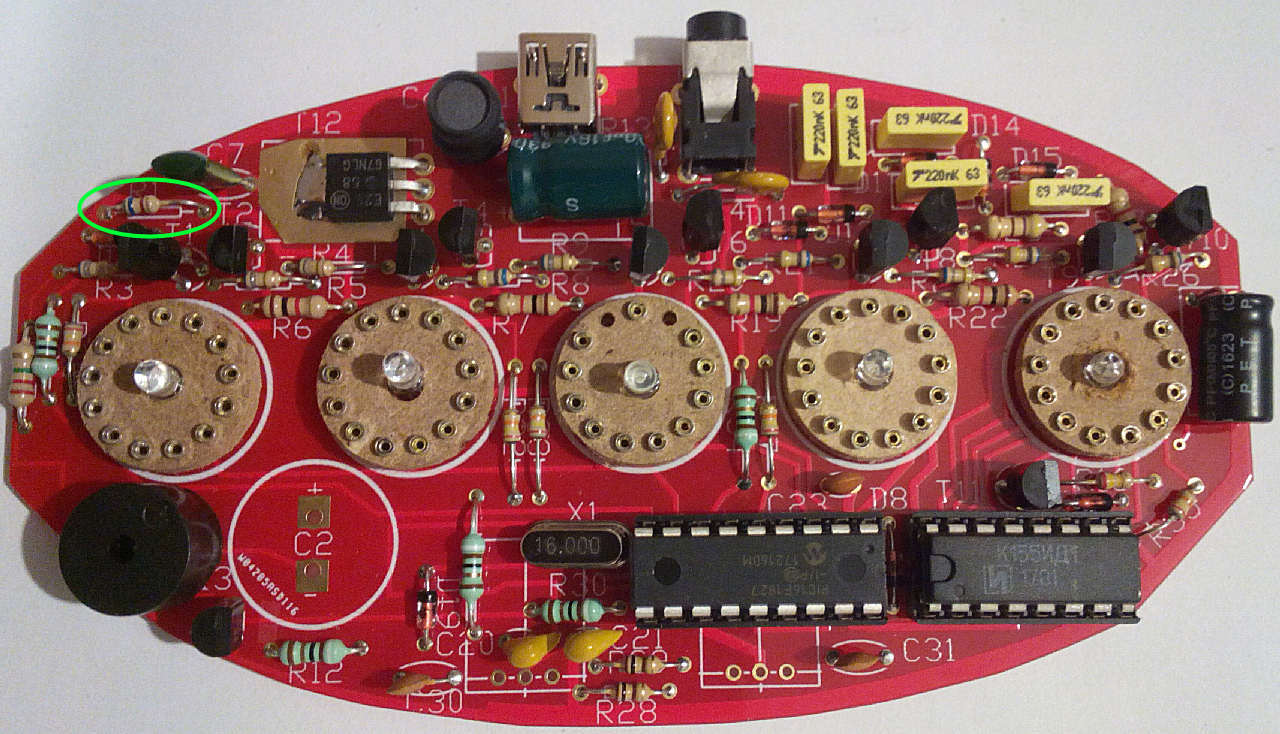
Fit the 5K6 resistor (green-blue-red) in the location marked for R1 as shown:
Re: BUTTON version PCB assembly - Bag1
Fit the 470r resistor (yellow-purple-brown) in the location marked for R25 as shown:
Re: BUTTON version PCB assembly - Bag1
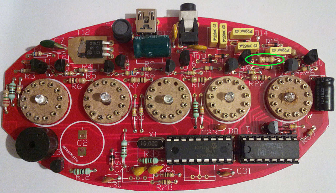
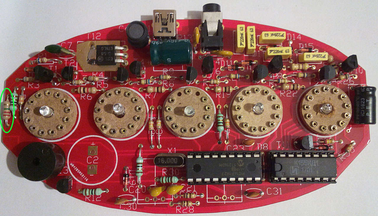
Fit the 240k (red yellow yellow) or 270k (red violet yellow) in the location marked for R16 as shown:
Re: BUTTON version PCB assembly - Bag1
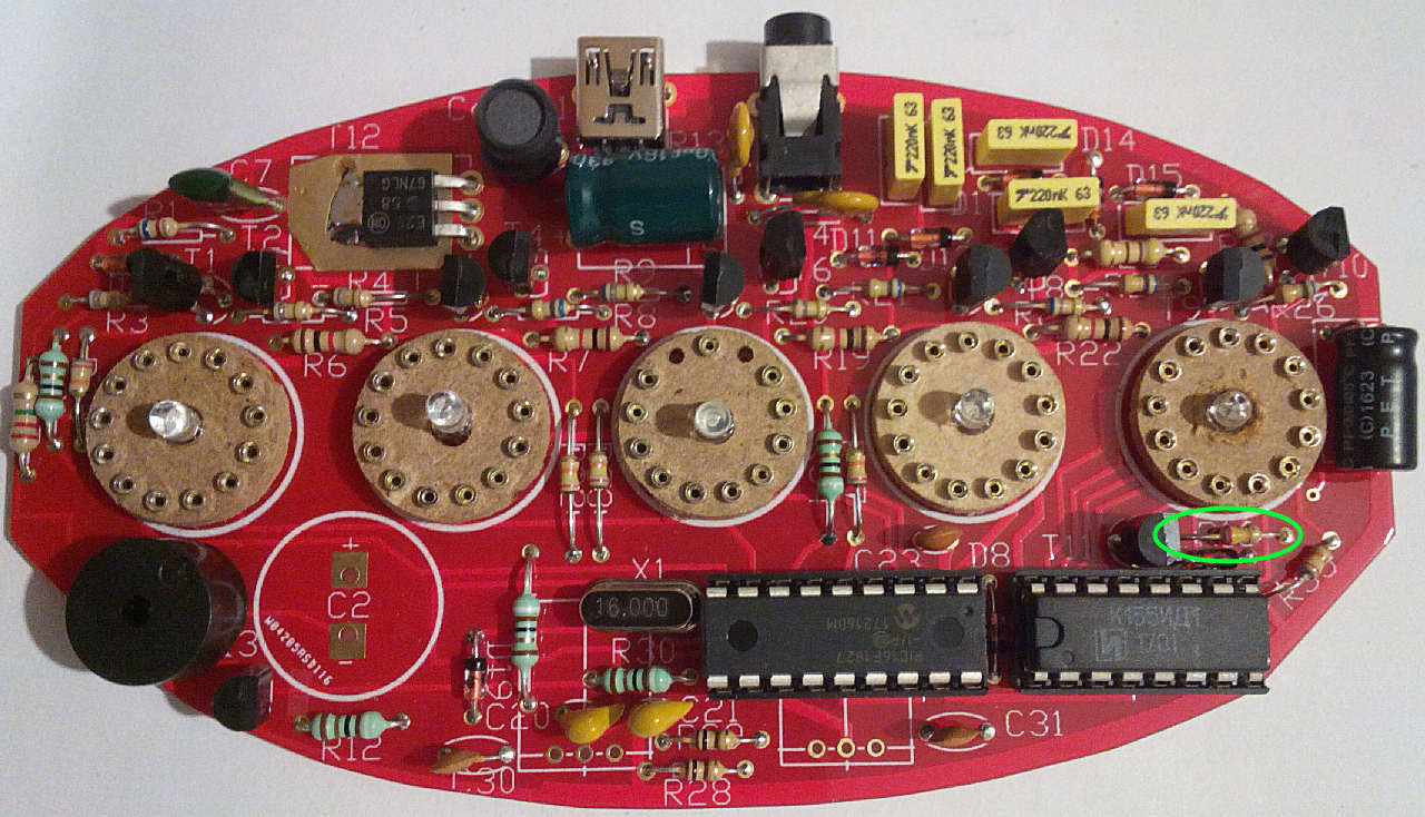
Fit the 2M2 resistor (red-red-green) in the location marked for R37 as shown:
Re: BUTTON version PCB assembly - Bag1
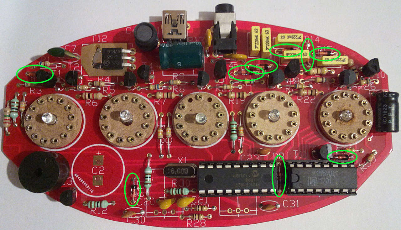
Fit the 9x 1N4148 diodes in locations marked for D8,10,11,12,13,14,15,16,19 as shown: **NOTE** the band marked on the end of the diode body must face the same way as shown in the photograph, this is also indicated on the PCB with a thick white band.
Re: BUTTON version PCB assembly - Bag1
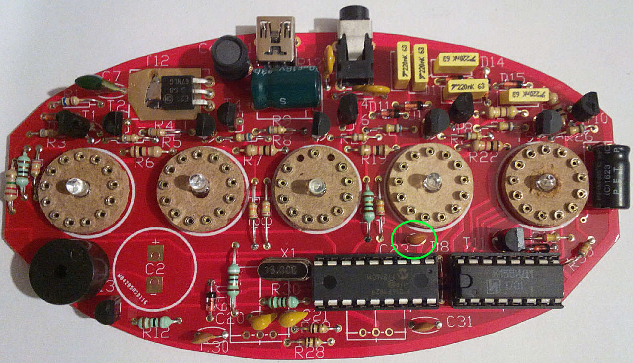
Fit the brown 10n (marked 103) or 33n (marked 333) ceramic capacitor in the location marked for C23:
Re: BUTTON version PCB assembly - Bag1
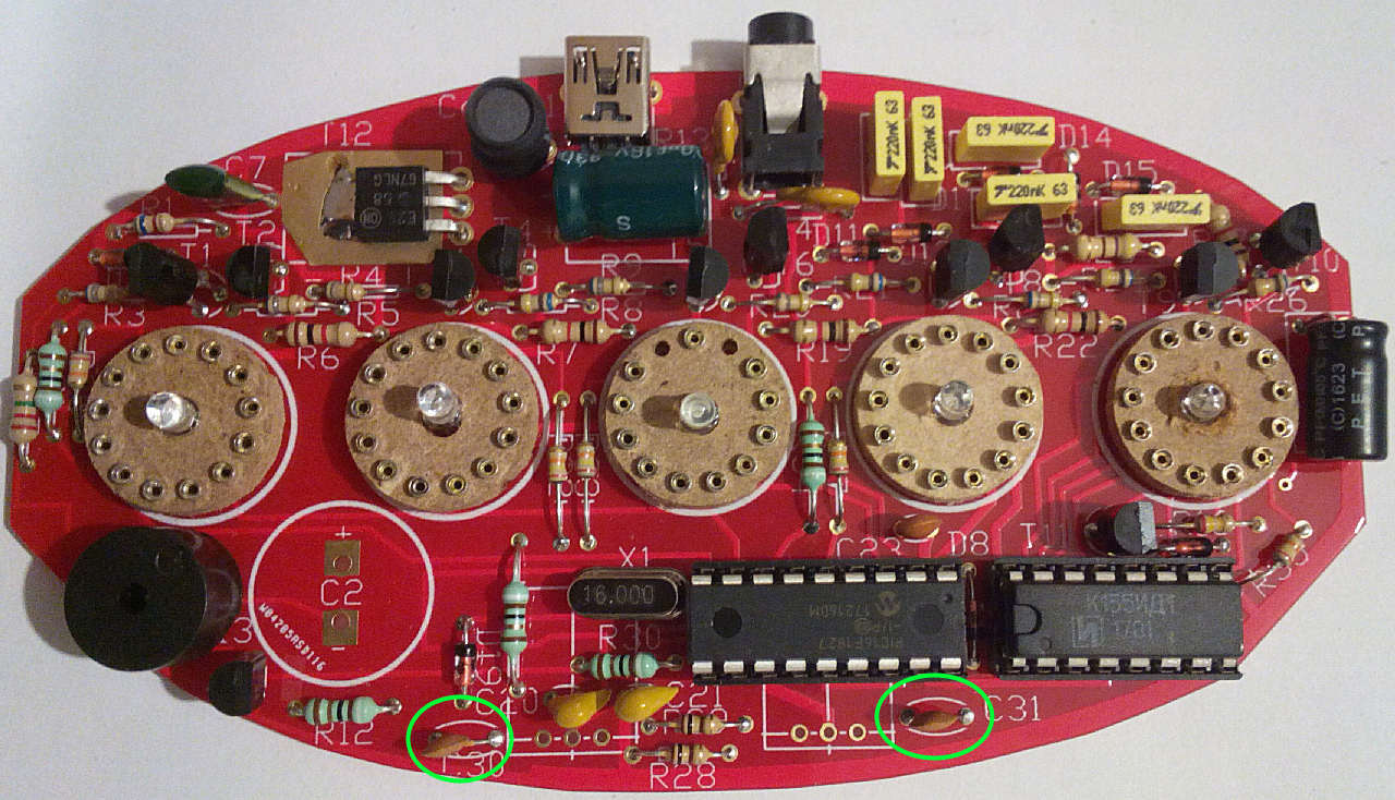
Find the 2x tiny electrolytic capacitors (small black cylinder marked 33u 16V) and fit them in the locations marked C30,31. The picture shows ceramic capacitors but has since been modified to use a larger value. The - band on the capacitor faces TOWARDS the touchswitch on both of these (away from the PCB sides):