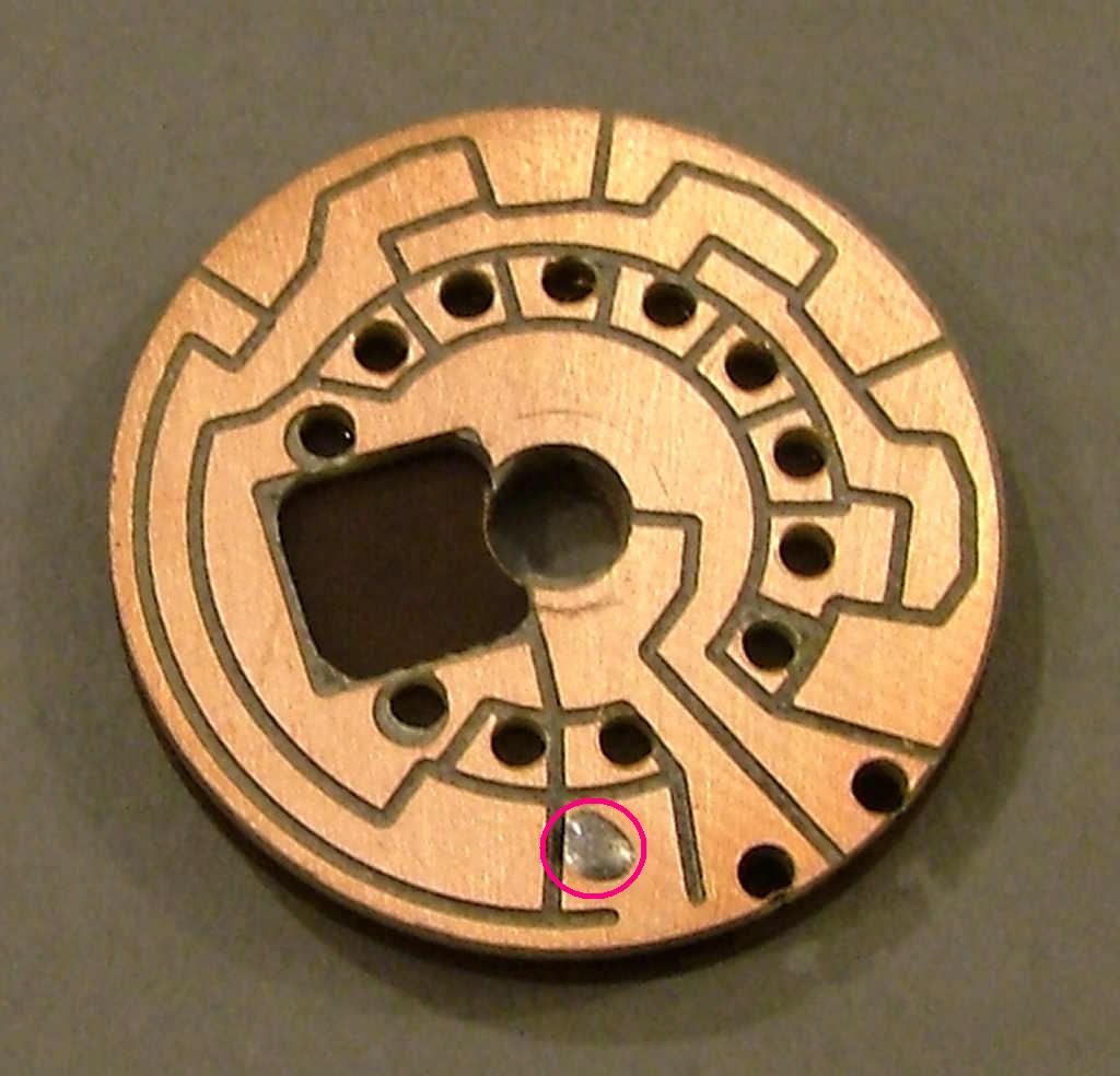
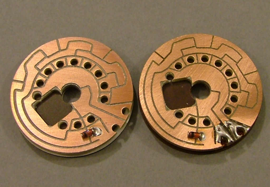
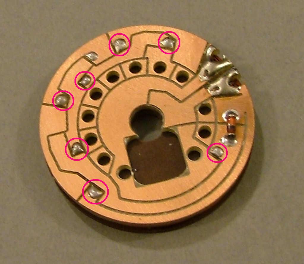
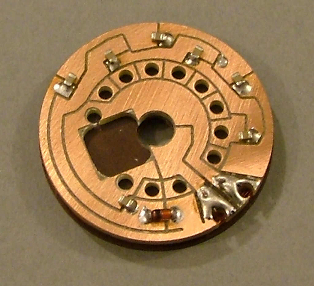
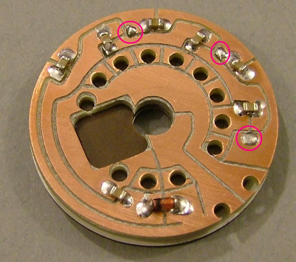
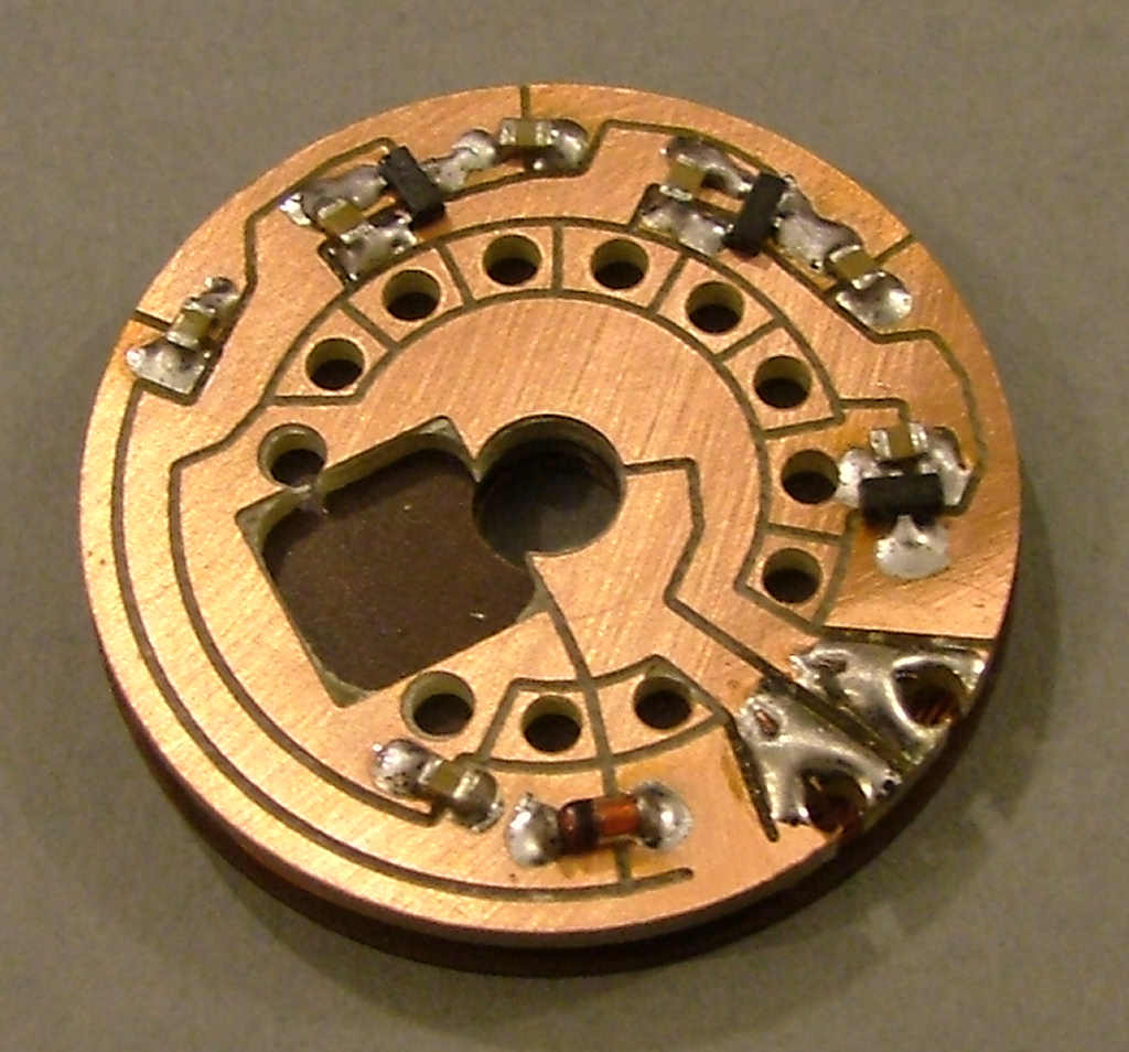
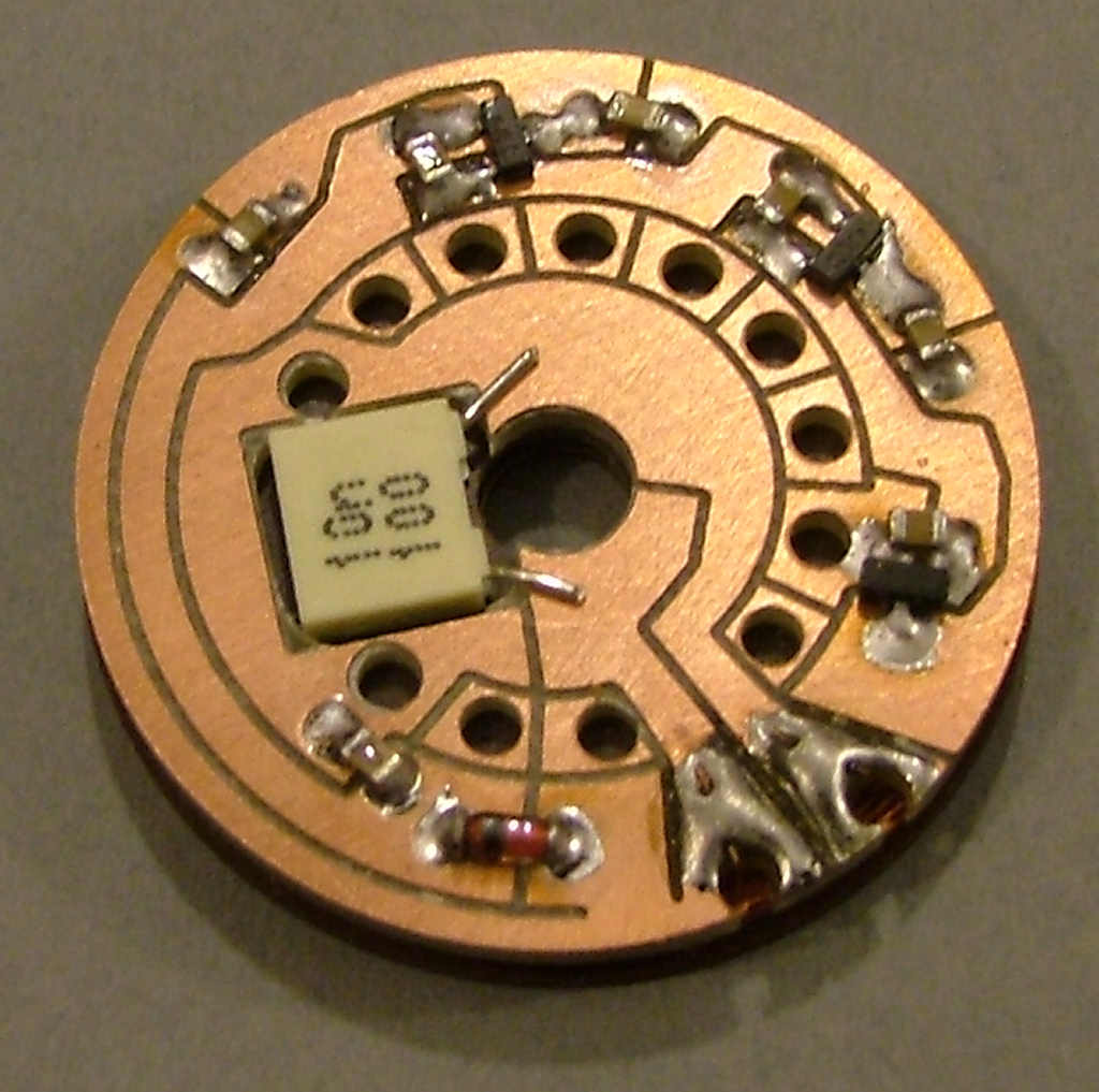
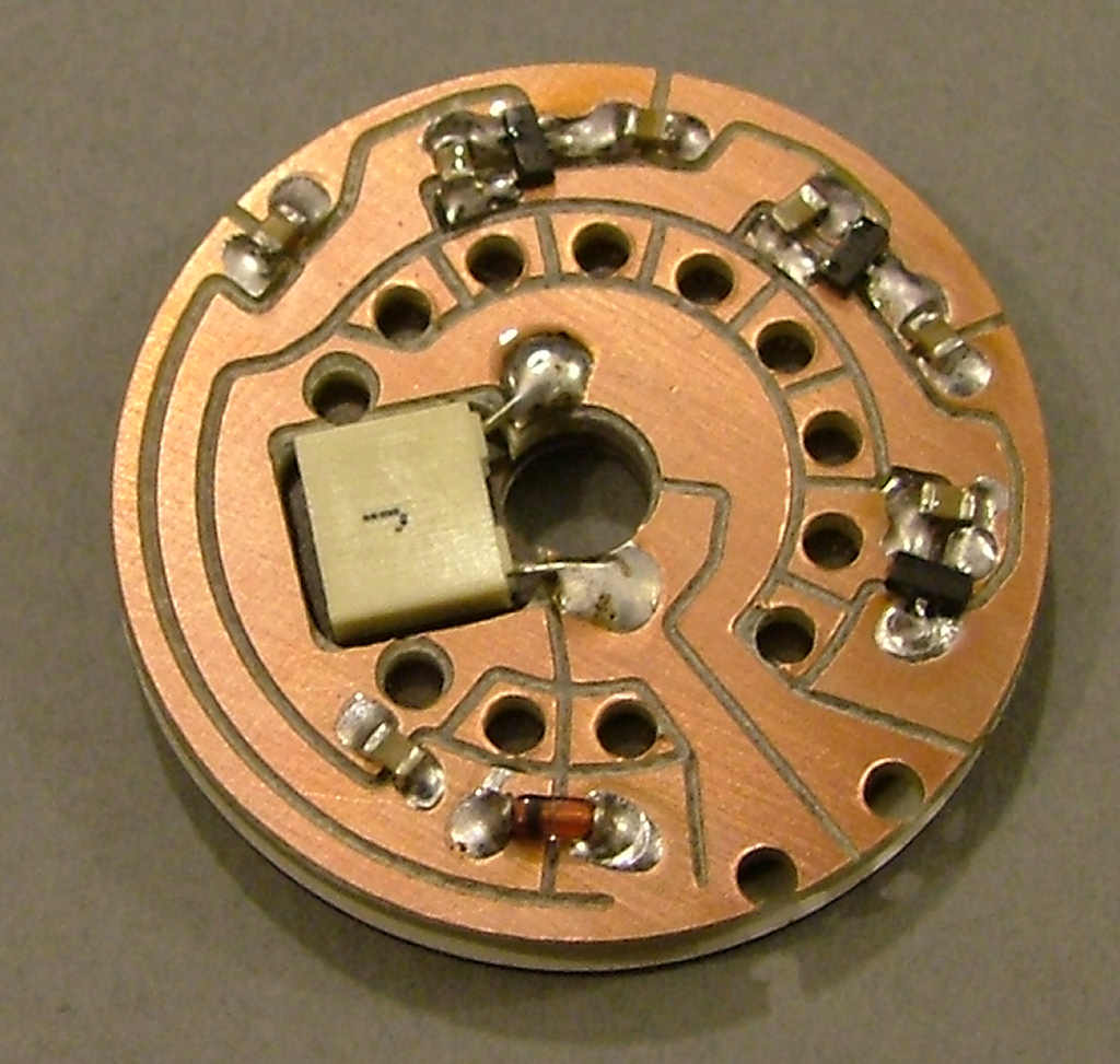
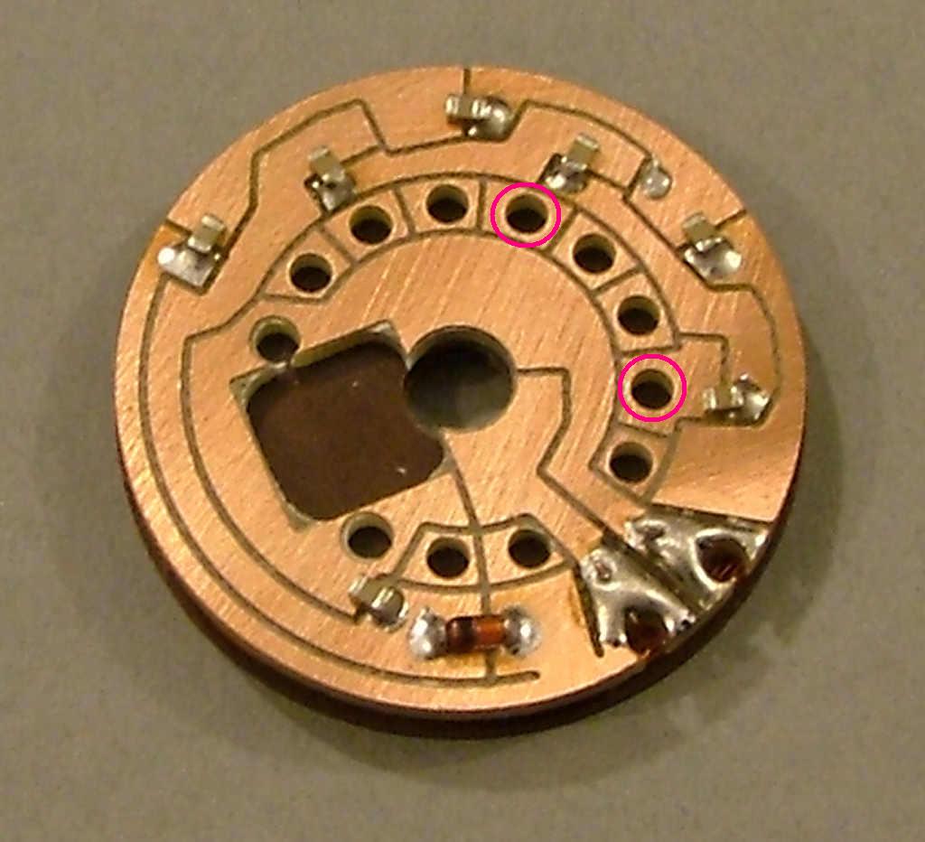
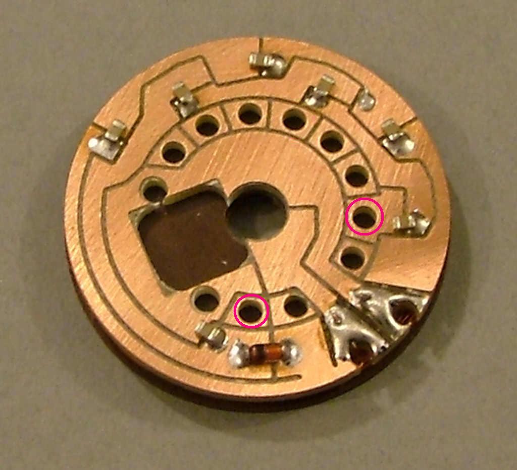
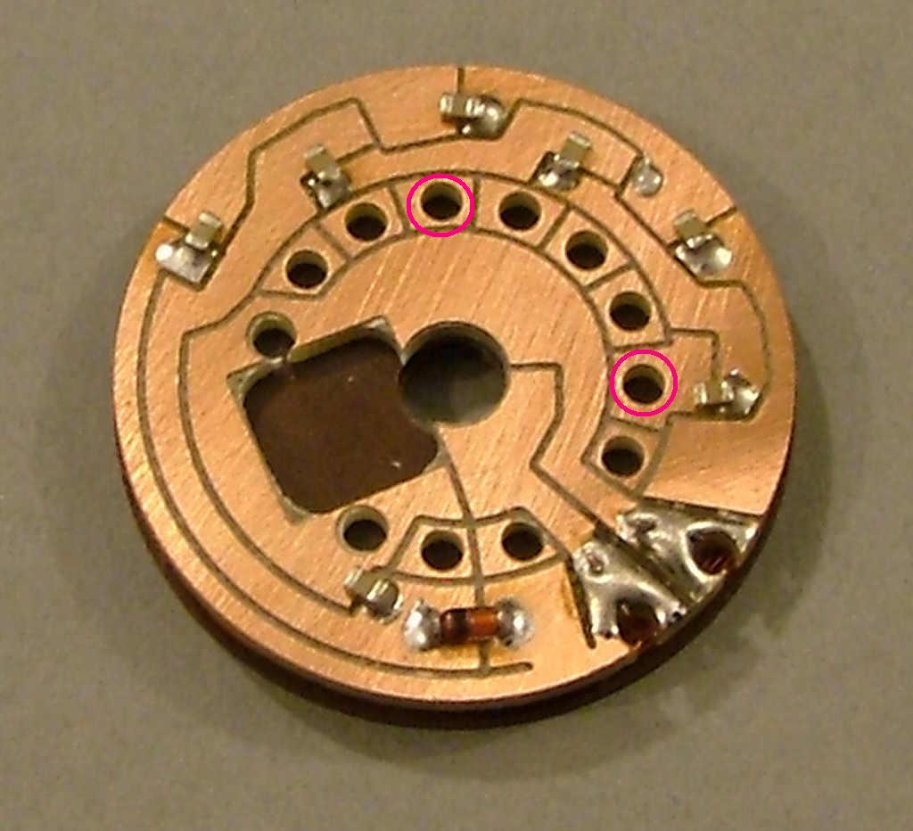
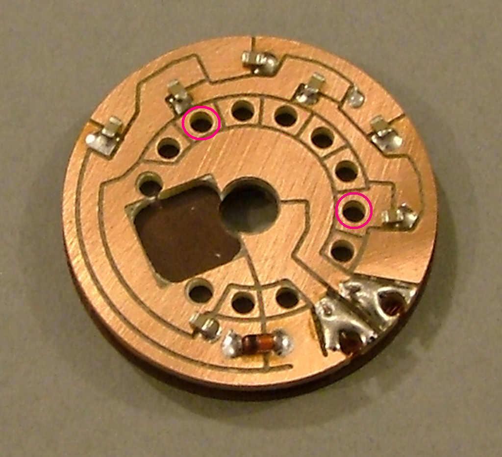
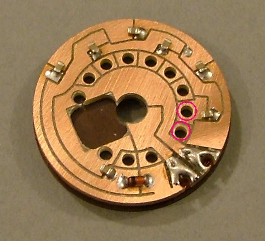
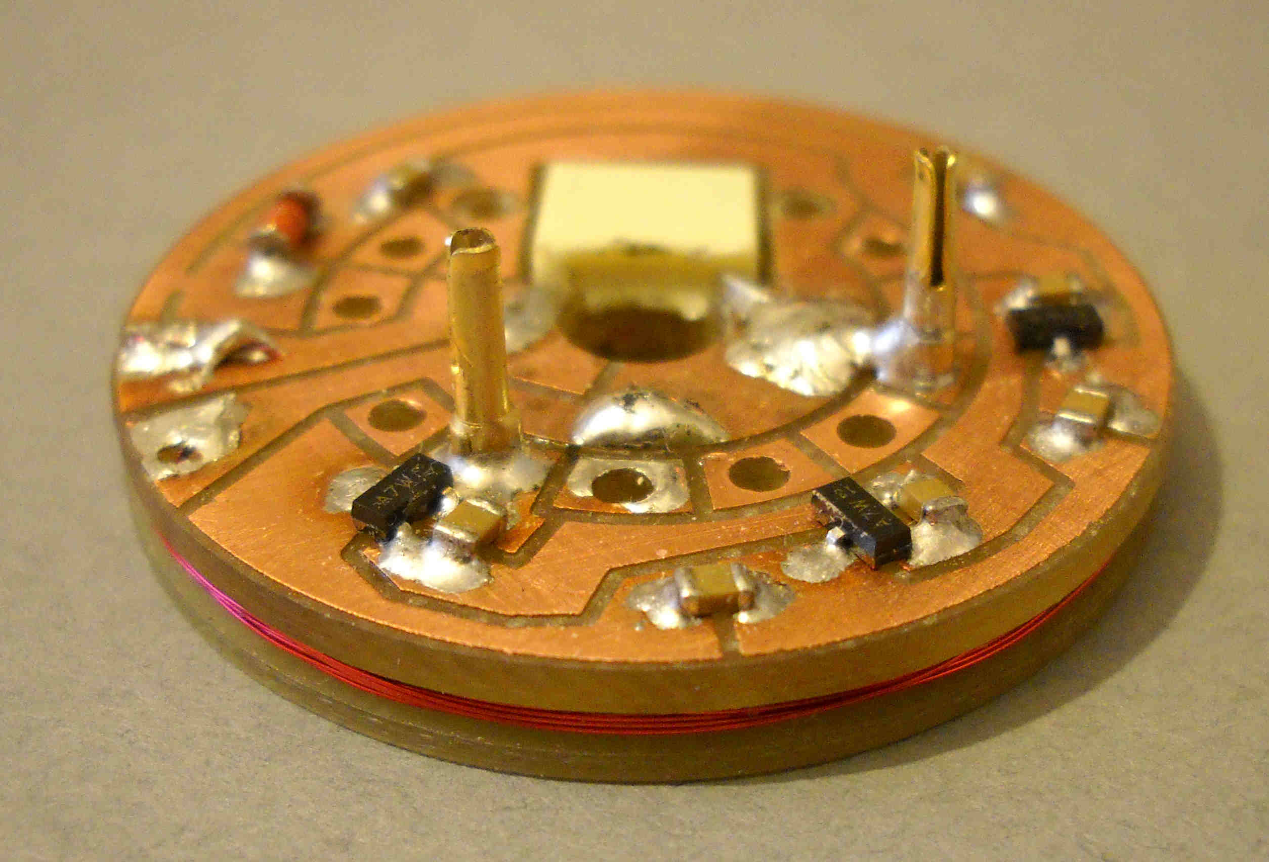
Piece display PCB
Posted: Sat Sep 15, 2012 2:40 am
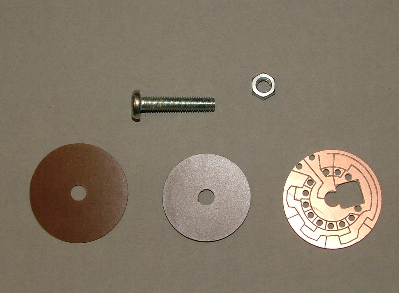
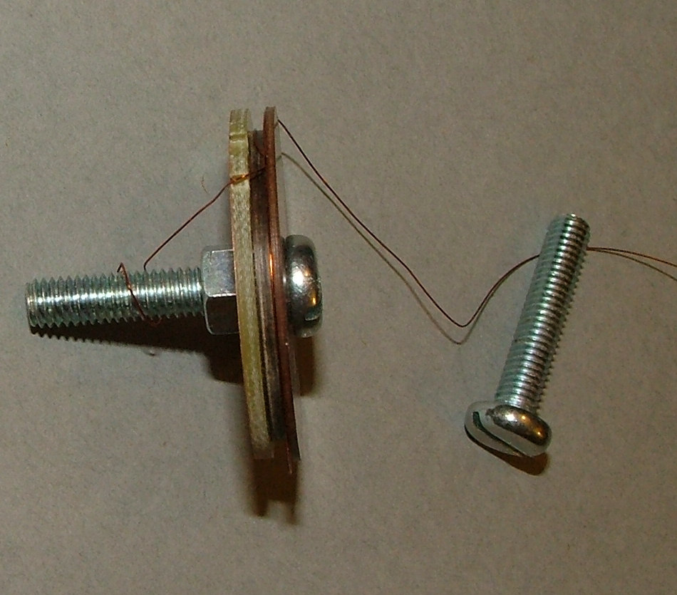
For this you will need the entire contents of BAG 4 plus the M5 nuts and bolts from BAG 1, solder from BAG 5 and copper wire.
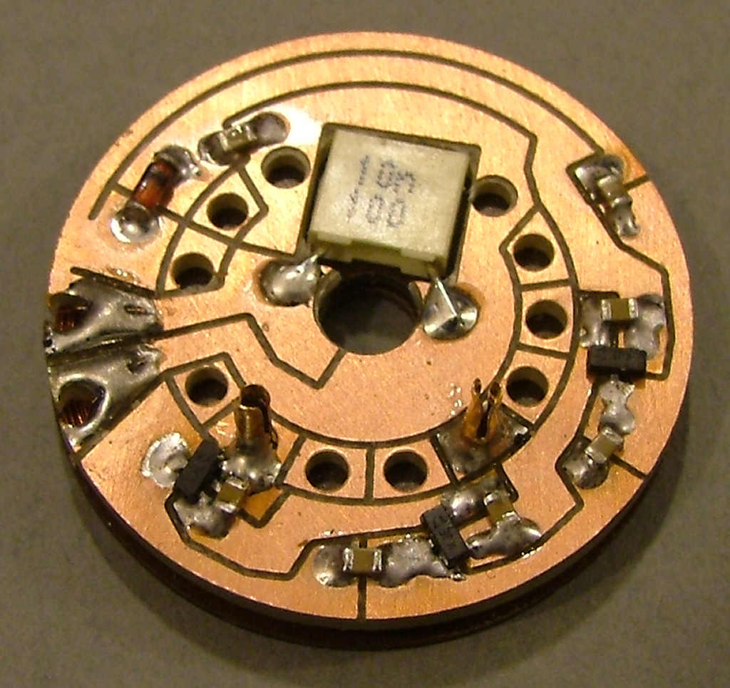
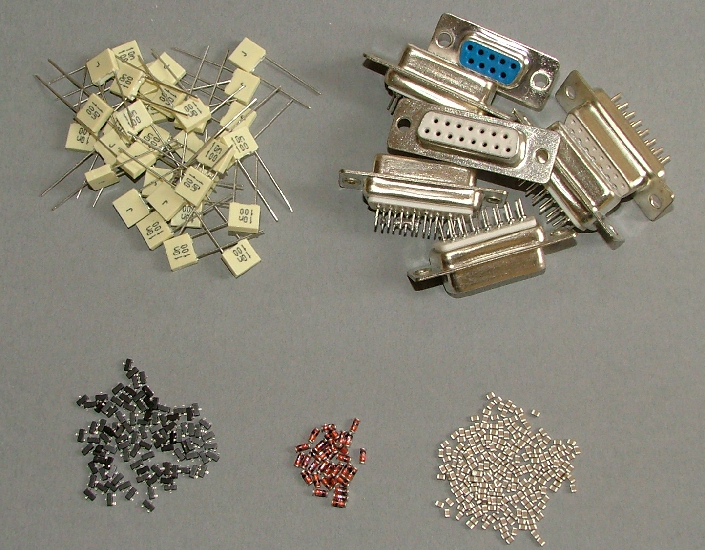
Remove the surface mounted components from their tapes. Only one of each type of part is used so there is no risk of mixing up different values or types.
You will have:
Dual diode packs - these are small rectangular 3-legged black plastic blocks. 3 are needed for each board.
Single diodes - Copper-orange glass cylinders with a black band marking one end. These are polarised and must face the same way as on the example baord. One is needed for each board.
Capacitors - Beige rectangular ceramic blocks. Seven of these are used on each board.
Separate the foil cpacitors into another pile, these are cream plastic blocks with 2 wires and '10n' marked on them and the 'D' connectors into another pile. Put these piles of components to one side until the coil winding is done.

