Page 1 of 2
PCB Assembly discussion
Posted: Sun Aug 03, 2014 1:02 am
by Tony
Suggestions for improvements, mistakes, hints here please.
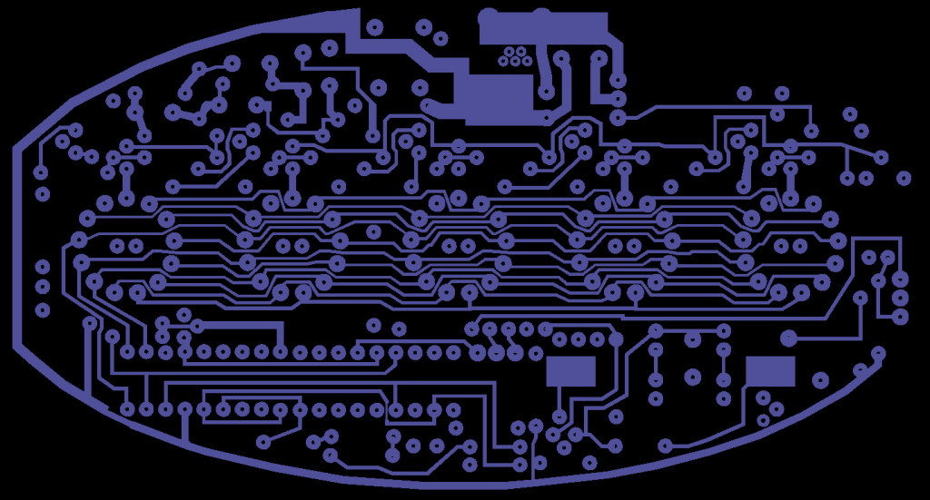
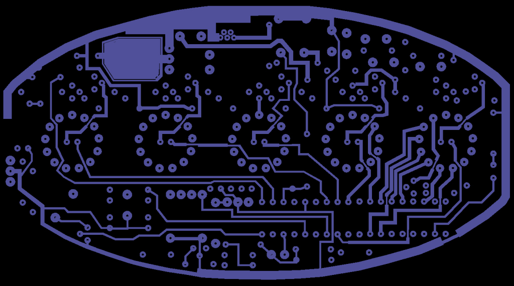
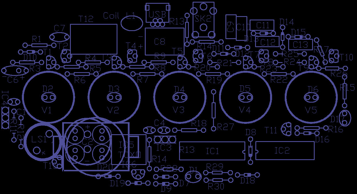
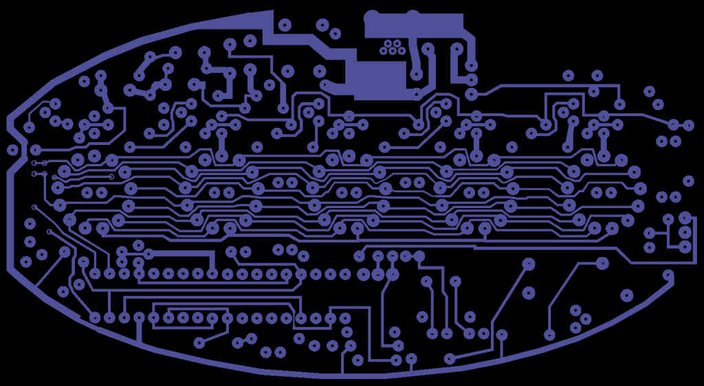
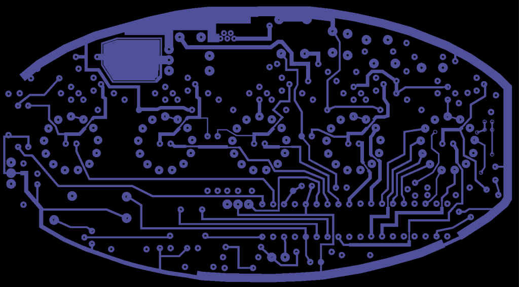
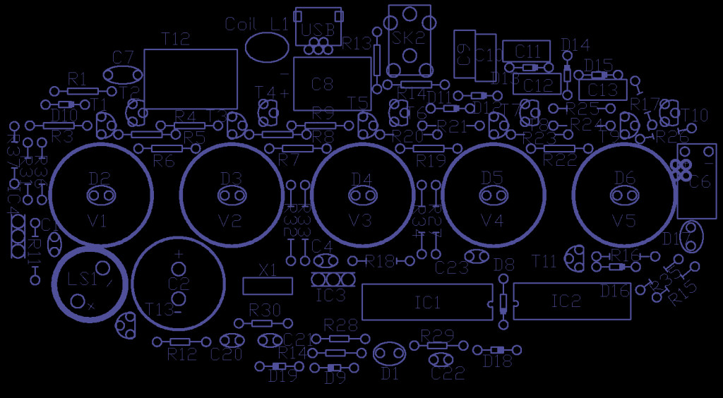
I've posted an image of the PCB track Gerbers here to help tracing faults.
V1 BOTTOM:
V1 TOP:
V1 Component overlay:
V2 BOTTOM:
V2 TOP:
V2 component overlay:
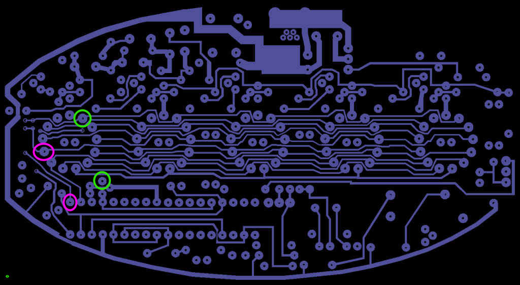
If the '8' or DPs aren't working you may have cut through the track when removing the through-hole links. If so use a short piece of insulated wire to link the pads indicated here, pink for '8' and green for DPs:
.
Re: PCB Assembly discussion
Posted: Mon Aug 11, 2014 9:44 am
by Higginz
Hey Tony
I've begun to build the clock kit this past weekend, so far so good. I've only run into one issue with the assembly. The included socket for IC1 was incorrect. The kit contained (2) 16 pin sockets rather than (1) 16 pin and (1) 18 pin socket. Not really a big deal, I was tempted to mount IC1 directly to the board but decided not to as I've had bad luck with removing soldered ICs. I ended up using a 20 pin socket from my own stash of parts and trimmed it down to fit.

Re: PCB Assembly discussion
Posted: Tue Aug 12, 2014 12:21 am
by Tony
Now that has me worried

it's one of those things that just shouldn't happen as the 16 and 18 pin sockets are added in different stages to avoid just this. I hope a tube of 16 pins hasn't been mixed up with the 18 pins.
I'm pleased you managed to work around it, 18 is one of those tricky sizes to make up.
Re: PCB Assembly discussion
Posted: Wed Jan 14, 2015 4:10 pm
by maclark88
Tony, on the Bag 1 parts instructions it refers to a r251. This should be r25.
Re: PCB Assembly discussion
Posted: Wed Jan 14, 2015 6:21 pm
by Tony
Thanks for letting me know, I've edited it. One day I might put together a kit scary enough to use over 250 resistors but not just yet

Re: PCB Assembly discussion
Posted: Wed Jan 21, 2015 3:48 am
by Squigglyline
Hi Tony,
I have reached the point of testing the clock and although all 5 led's do light, they're significantly dimmer than they should be. The IR sensor does work but the LED output is off. This is both before and after the crystal mod. Any ideas?
Re: PCB Assembly discussion
Posted: Wed Jan 21, 2015 9:50 pm
by maclark88
Squigglyline wrote:Hi Tony,
I have reached the point of testing the clock and although all 5 led's do light, they're significantly dimmer than they should be. The IR sensor does work but the LED output is off. This is both before and after the crystal mod. Any ideas?
I might suggest checking the polarity of all diodes.
Re: PCB Assembly discussion
Posted: Thu Jan 22, 2015 3:17 am
by Squigglyline
maclark88 wrote:Squigglyline wrote:Hi Tony,
I have reached the point of testing the clock and although all 5 led's do light, they're significantly dimmer than they should be. The IR sensor does work but the LED output is off. This is both before and after the crystal mod. Any ideas?
I might suggest checking the polarity of all diodes.
Thanks very much for the suggestion maclark88! I definitely appreciate it. As far as I can tell, the polarity is correct. Here's links to pics of my board in the event you might see anything obvious that I am overlooking...
http://i61.tinypic.com/30jljli.jpg
http://i61.tinypic.com/2iw3y8j.jpg
Again, thank you!!
Re: PCB Assembly discussion
Posted: Thu Jan 22, 2015 3:59 am
by Tony
How dim are they?, they're driven at a low on cycle so won't appear to be bright. Check the processor is receiving about 4-4.5V at pin 14, also as you have L1 in place carefully check for 190V on R25.
Re: PCB Assembly discussion
Posted: Fri Jan 23, 2015 4:08 am
by maclark88
Squigglyline wrote:maclark88 wrote:Squigglyline wrote:Hi Tony,
I have reached the point of testing the clock and although all 5 led's do light, they're significantly dimmer than they should be. The IR sensor does work but the LED output is off. This is both before and after the crystal mod. Any ideas?
I might suggest checking the polarity of all diodes.
Thanks very much for the suggestion maclark88! I definitely appreciate it. As far as I can tell, the polarity is correct. Here's links to pics of my board in the event you might see anything obvious that I am overlooking...
http://i61.tinypic.com/30jljli.jpg
http://i61.tinypic.com/2iw3y8j.jpg
Again, thank you!!
I didn't see anything out of the ordinary. When you say the led is off, which led are you referring to?


