Page 1 of 2
Piece display PCB
Posted: Sun Dec 07, 2014 4:54 am
by Tony
For this you will need the entire contents of BAG 4 plus solder from BAG 5.
230x Diodes - Copper-orange glass cylinders with a black band marking one end. These are polarised and must face the same way as in the photographs.
Capacitors - Brown ceramic discs. Seven of these are used on each board.
Capacitors - Green rectangles. One of these is used on each board.
Coils - Black plastic sleeved ceramic-like material. One of these is used on each board.
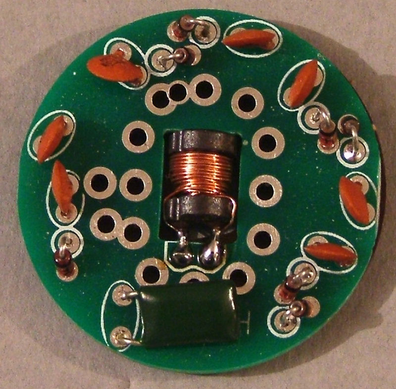
Re: Piece display PCB
Posted: Sun Dec 07, 2014 4:58 am
by Tony
First fit the 7 ceramic capacitors:
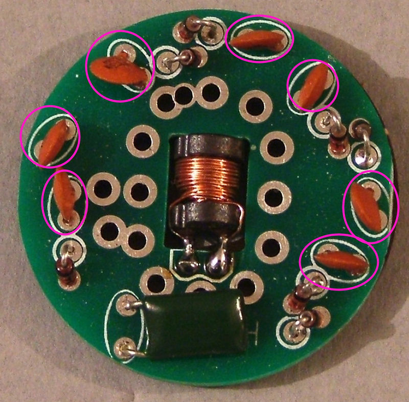
Re: Piece display PCB
Posted: Sun Dec 07, 2014 4:59 am
by Tony
Next the 7 diodes, the band FACES the CIRCLED HOLE, that is the wire leading from the banded end foes through the hole marked with a circle:
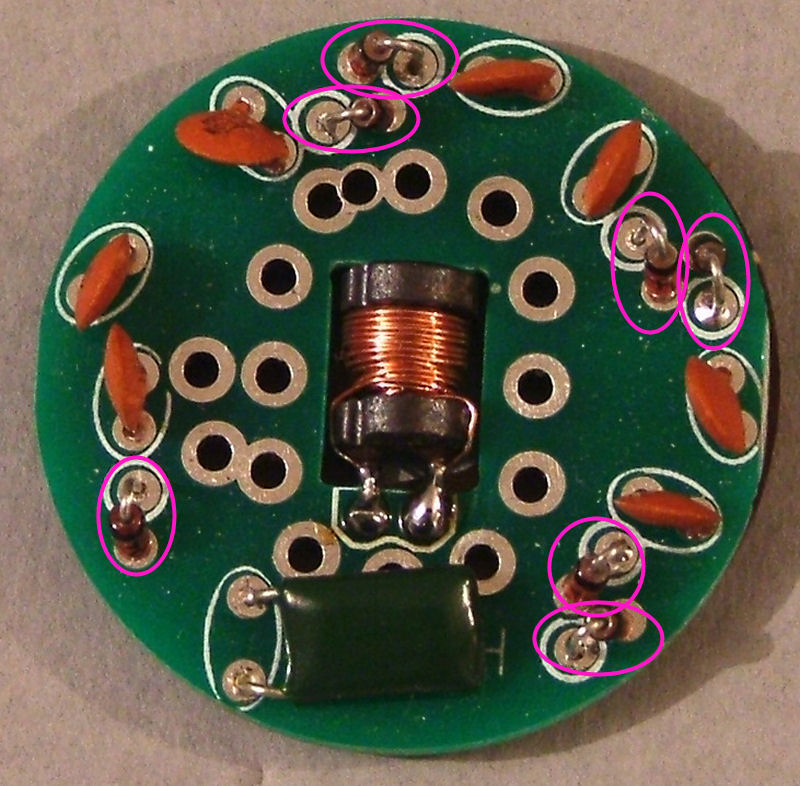
Re: Piece display PCB
Posted: Sun Dec 07, 2014 5:01 am
by Tony
Then the 4n7 green capacitor:
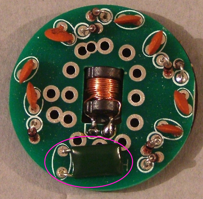
Re: Piece display PCB
Posted: Sun Dec 07, 2014 5:03 am
by Tony
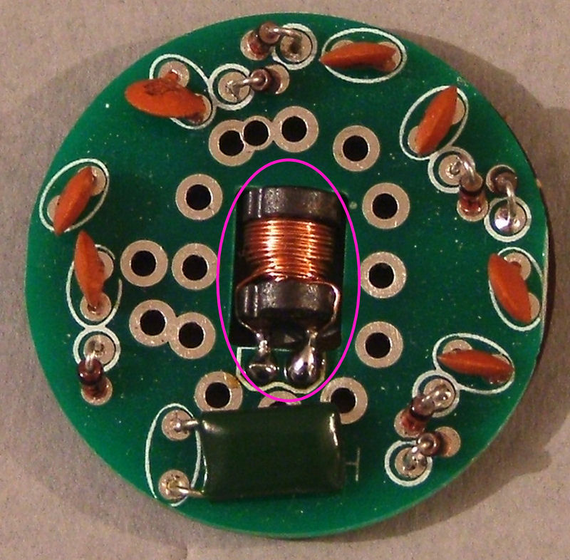
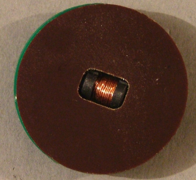
Finally, the prewound inductor. You'll need to carefully remove the protective plastc sleeve from it first.
Use one of the paxolin base covers to make sure it's at the right depth through the hole in the PCB. You want it to be just level with the bottom of the base cover.
Re: Piece display PCB
Posted: Sun Dec 07, 2014 5:06 am
by Tony
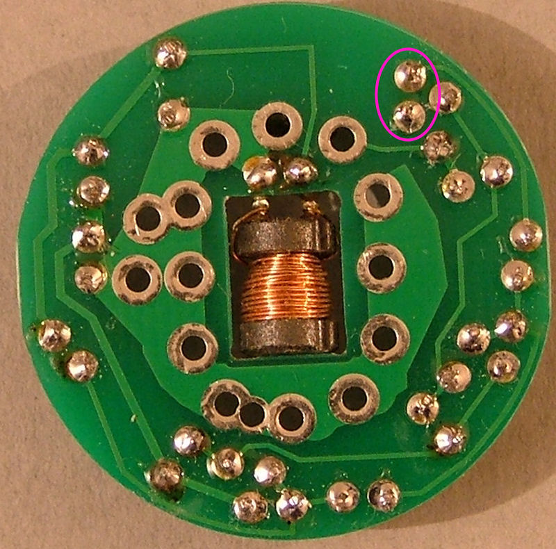
Finally bridge these two pads with some solder:
Re: Piece display PCB
Posted: Sun Dec 07, 2014 5:07 am
by Tony
Dismantle the three 25 way 'D' sockets, the easiest way is to cut through one of the rivets then seperate the two halves of the shell.
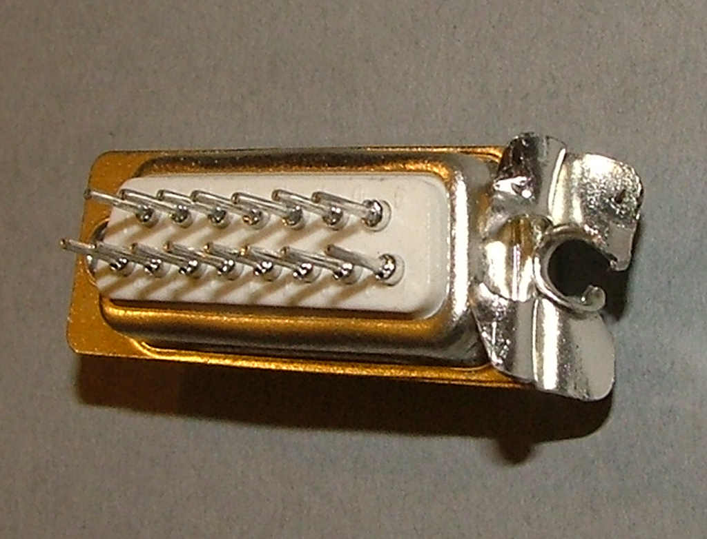
Open up the socket housing and remove the pins.
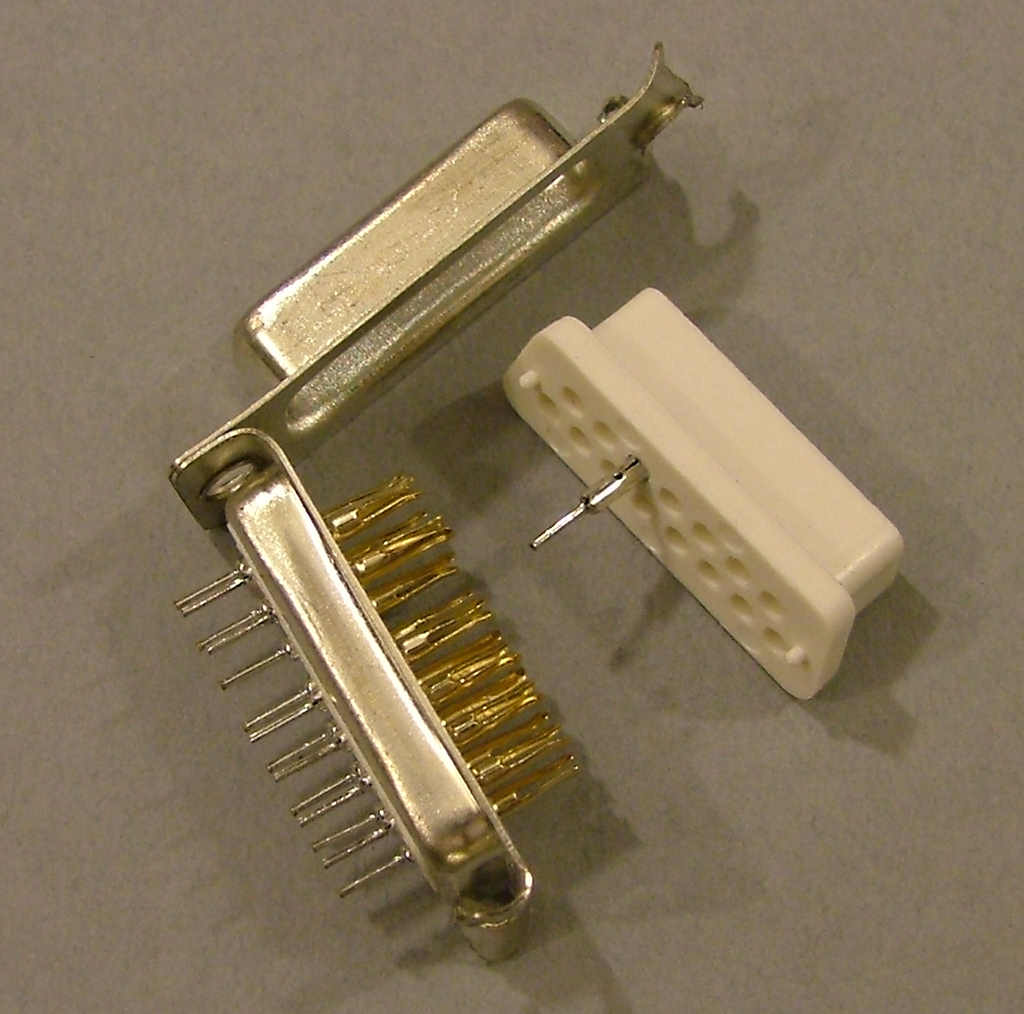
Re: Piece display PCB
Posted: Sun Dec 07, 2014 5:11 am
by Tony
Fit two pins as shown and solder in place.
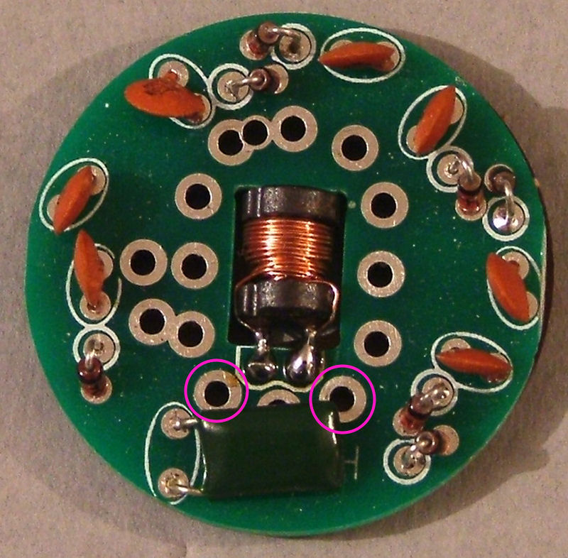
Make four of these for use with 4x IN-15Bs: Bishops (Alfiere)
Re: Piece display PCB
Posted: Sun Dec 07, 2014 5:12 am
by Tony
Fit two pins as shown and solder in place.
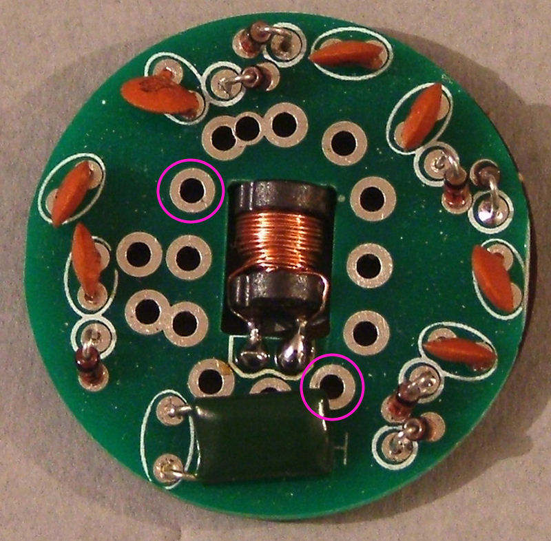
Make two of these for use with 2x IN-15As: King
Re: Piece display PCB
Posted: Sun Dec 07, 2014 5:13 am
by Tony
Fit two pins as shown and solder in place.
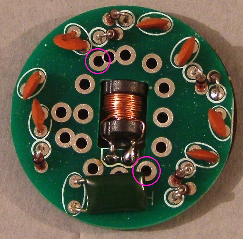
Make six of these for use with 4x IN-15As: Knight (Marchog) and 2x IN-15Bs: Queen (Vizier)


