Page 1 of 2
Board PCBs
Posted: Thu Dec 11, 2014 12:43 am
by Tony
For this you will need the entire contents of BAG 5 and the 4 base PCBs:
Unpack and sort out the components into seperate piles. You should have:
2x 22k 1/4W Resistors[/*]
2x 1k2 1/4W Resistors[/*]
1x 4A quickblow Fuse[/*]
16x Ferrite filters (chokes)[/*]
65x 100uH Inductors[/*]
65x 4n7 capacitors (Green)[/*]
66x 10n Ceramic capacitors (Brown)[/*]
52x 33u 16v Electrolytic capacitors[/*]
14x 14V Zener Diodes[/*]
2x 5v1 Zener Diodes[/*]
1x Power socket[/*]
60x 2.5mm PCB interconnect pins[/*]
15-20g Lead free 'solder'[/*]
16x Coil driver PCBs[/*]
2x 'Spine' PCBs[/*]
We'll start by assembling the 'spine' PCBs as these provide the power and drive signals for the coil drivers.
Before starting on the assembly, there's a small mistake in the PCB layout. The track next to F1 needs to be cut as it was moved by accident in the final layout and shorts the 12V rail to ground.
Cut it as shown here on both boards:
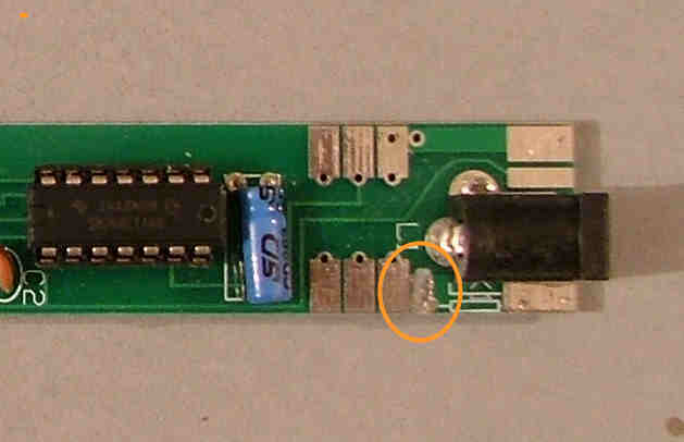
.
Re: Board PCBs
Posted: Fri Dec 19, 2014 12:59 am
by Tony
First of all solder each the two 1k2 resistors (Brown red red) in the two R1 positions:
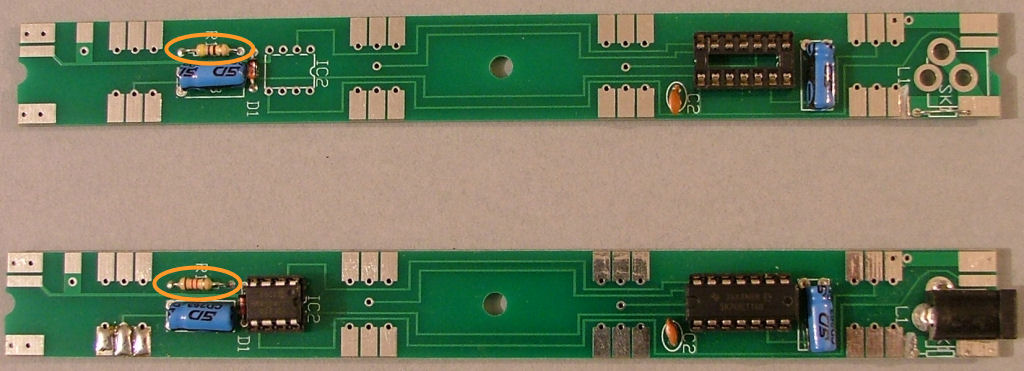
R2, a 22K resistor (Red red orange) x2 is missing from the PCB layout and needs to be patched on underneath each of the PCBs as shown here, between pins 1 and 7 of both IC1s:
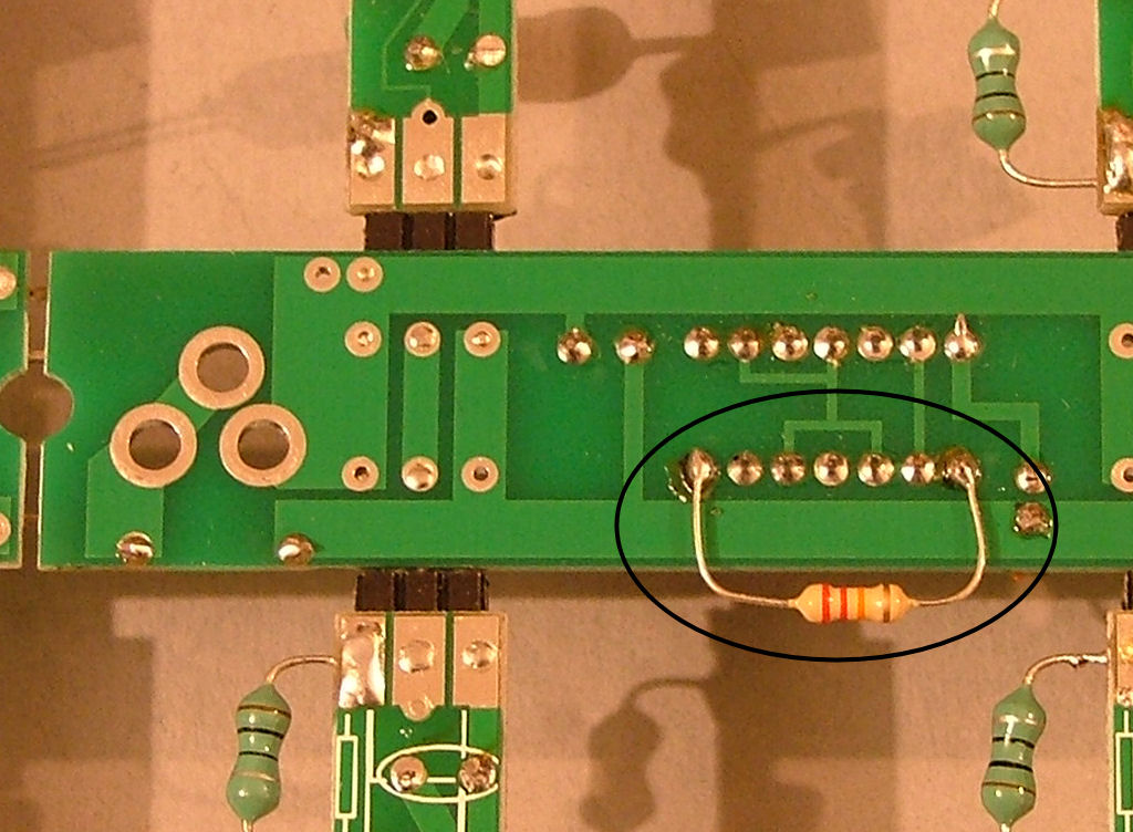
Re: Board PCBs
Posted: Fri Dec 19, 2014 1:02 am
by Tony
Now the two 5v1 zener diodes (from the strip of 2 copper glass beads). These are polarised and the black band points up in the photograph:
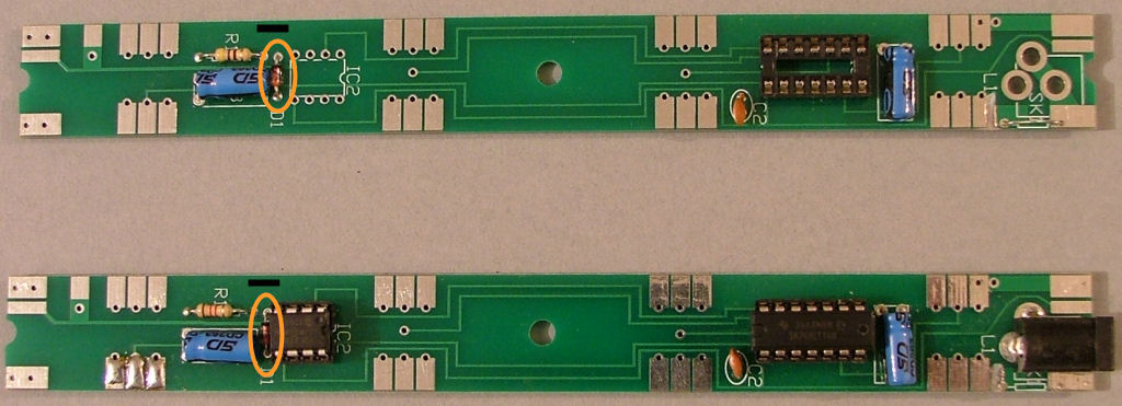
Re: Board PCBs
Posted: Fri Dec 19, 2014 1:03 am
by Tony
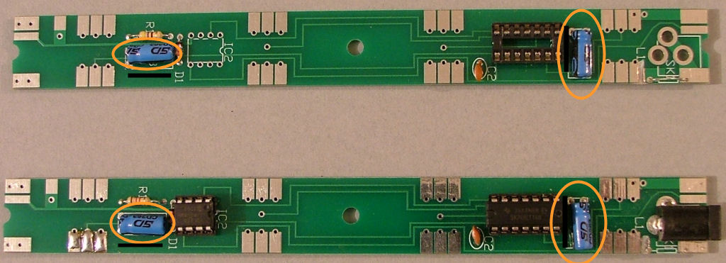
Now the four 47uF capacitors (blue or black aluminium cans) in the two C1 and C3 positions - again these are polarised and the black stripe faces the mark in the photos:
Re: Board PCBs
Posted: Fri Dec 19, 2014 1:05 am
by Tony
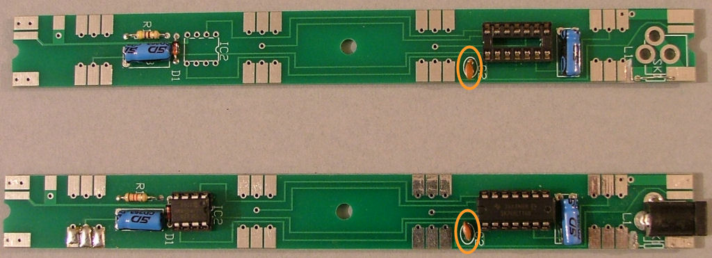
Next two brown 10n ceramic capacitors in the two C2 positions:
Re: Board PCBs
Posted: Fri Dec 19, 2014 1:12 am
by Tony
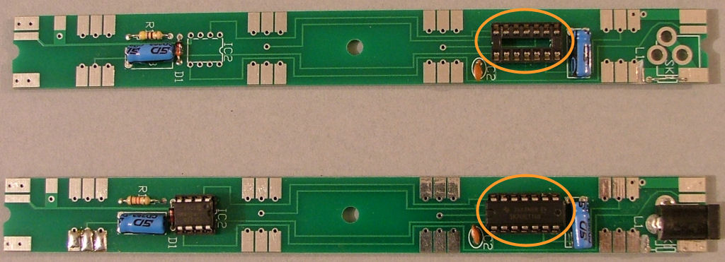
Almost complete - now solder the two 14 pin IC sockets into the IC1 positions on the PCB - there's a little notch which marks pin 1, that faces left in the photographs and matches the markings printed on the board::
Re: Board PCBs
Posted: Fri Dec 19, 2014 1:13 am
by Tony
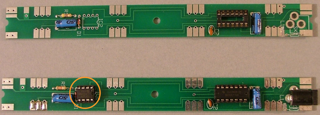
Now do the same with the 8 pin IC socket on one board. THis will be the master board which generates the drive signals:
Re: Board PCBs
Posted: Fri Dec 19, 2014 1:14 am
by Tony
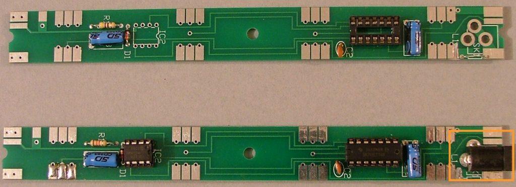
Finally solder the 12V power socket onto the PCB with the 8 pin IC socket:
Re: Board PCBs
Posted: Fri Dec 19, 2014 1:21 am
by Tony
Time for the first power on test. At this stage we need to check the 12V and 5V supplies are correct. DO NOT fit any of the ICs yet, even though they're shown in the photographs.
Connect a meter on a low mA range between the F1 pads here:
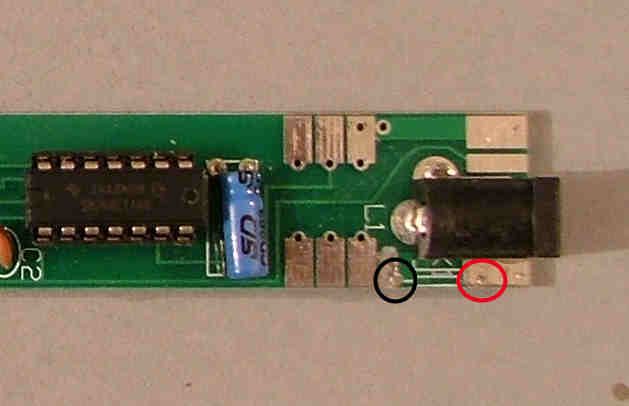
You have cut that track?. If so plug in the power supply (or use a bench supply if available) and switch on. After a second the green light on the power supply should light and your meter should show about 5-7mA for one spine PCB (10-15mA for both linked) being drawn. If there's nothing at all check your connections and the meter fuse. If there's a much higher reading or the green LED flashes check for solder bridges or D1/C1/C3 being in the wrong way round.
If that test went OK temporarily tack F1 into place or if you have a second meter just leave the first one in place. You now need to check the 5V supply is correct.
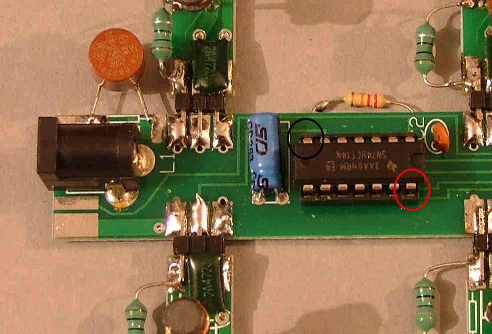
Connect a voltmeter between the IC socket pins shown - note the IC should NOT be in there just yet. You should have a reading of around 4.9-5.1V. If it's missing check connections and R1/D1, if it's too high (12V) you have probably used the wrong diode for D1.
Re: Board PCBs
Posted: Fri Dec 19, 2014 1:33 am
by Tony
If the tests have gone OK up to now we can link the secon spine PCB up and repeat them. Use 3 of the PCB header pins removed from the plastic spacer to join them, leaving a small gap of about 1mm (Ignore the driver PCBs soldered in place, the photos were taken using a completed assembly):
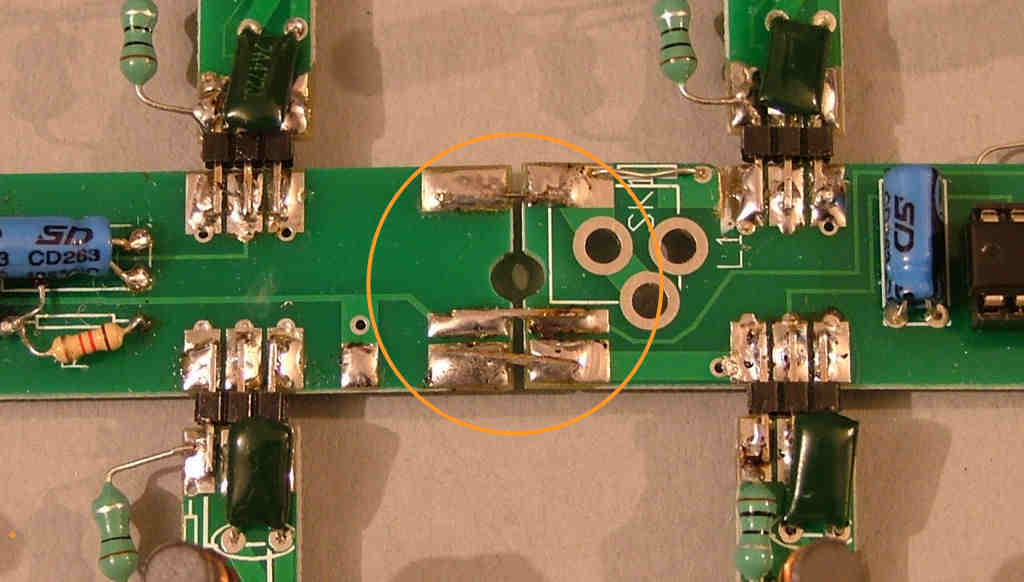
Use a piece of wire offcut to bridge the F1 pads on the second PCB as can be seen just above the SK1 silkscreen above.
Remove the tagged-on F1 from the first PCB if fitted and repeat the current test - it should now be about 20-25mA. Repeat the 5V test on both the first IC1 socket and the IC1 socket on the newly added second PCB and follow the previous hints if it's too high or low.
You should now have about 5V at the pins shown on both 14 pic sockets - if so we can now fit the ICs.
The two 74HCT14 buffers are fitted into the IC1 sockets with the notch matching the one in the socket and printed on the PCB (facing away from the 12V power connector).
The small 8-pin microcontroller is fitted in the IC2 socket, again making sure the pin 1 notch or dot matches the socket and PCB markings - it's the opposite way round to IC1 and faces the 12V connector.
Repeat the current test again - there should be very little change as these are low power devices. If it's more than 30mA switch off quickly and check they're the right way round and for solder bridges under the sockets.


