PCB assembly - Nixies
Posted: Mon Sep 07, 2015 3:24 am
Start with the pack of 2x nixies (1x IN-19B and 1x IN-8-2), take them out of their packing and straighten the wires, spreading them out slightly to match the diameter of the socket. If any are uneven or slightly longer than the others you can trim them a little to match.
Note the white ceramic paint on one of the wires inside the IN19, at the back. This is the anode and must face directly to the back of the PCB when fitted. Ignore the short wire stub at the front of the IN-19, it's a second anode which isn't counted as a real pin and can be removed if preferred.
The same 'anode' lead is missing from the IN-8-2 nixies though it faces the same way - so the gap in the pins is positioned over the '12 o'clock' socket pin, leaving it unused.
Take the numerical nixie tube from the pack of 2:
If you received a kit without sockets, now is the time to push the socket pins onto the nixie wire ends, then insert them into the PCB and solder in place.
Starting with that gap where the anode wire would have been, position it over the topmost hole of the socket in the V5 position then push one wire in sequence into each hole. Make sure the missing lead 'gap' is still in the correct place, it's easy to slip one place whilst fighting (or fitting) it in. Push it down carefully into the socket pins until it sits on top of the LED - this acts as a spacer holding it above the PCB in the correct place. (You can fit them in any order you're happy with, I usually work from right to left).
This is shown on the thermometer PCB but the sockets are used in an identical way in the clock:
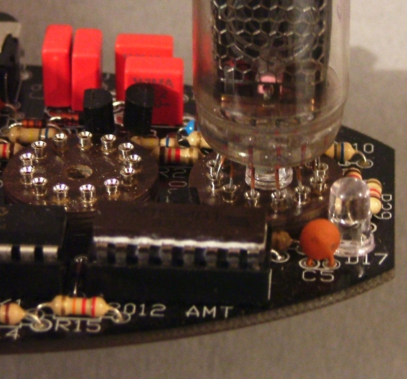
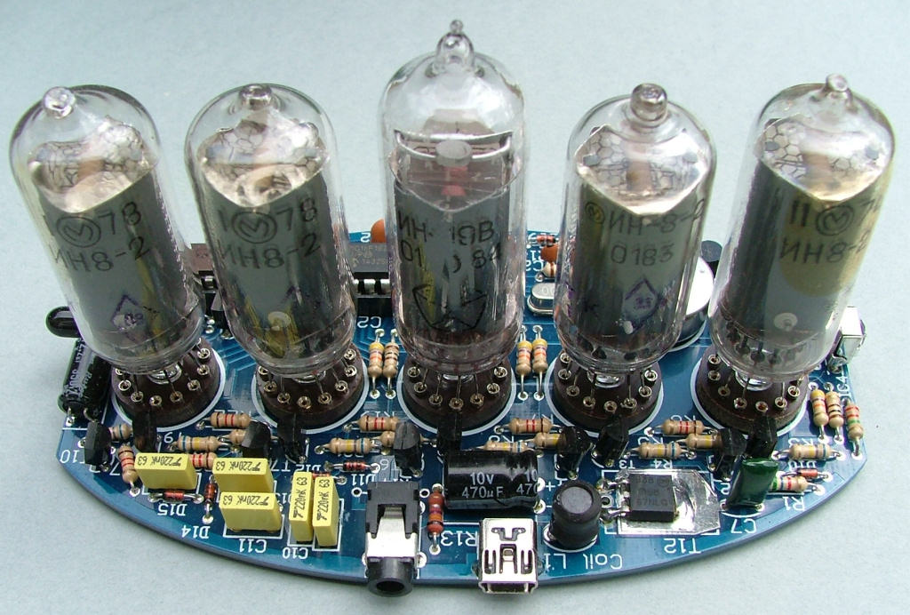
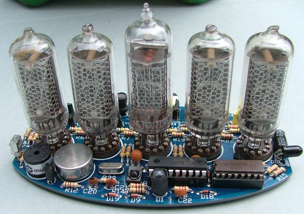
Take the 3x IN-8-2 nixies out of their packing and straighten the wires as before. Fit one into the socket for V4, next to V5 and fit the IN-19B(V) tube into the V3 socket, followed by the remaining 2x IN-8-2 nixies in V2 and V1. You should now have 2 pairs of numerical tubes separated by a symbol tube in the centre.
Once you're certain they're in the right places and are vertically aligned you may wish to solder 2-3 of the wires into the socket pins to prevent them being dislodged, though in everyday use they will stay in the sockets as the 12-13 wires combined have quite a tight hold.
Note the white ceramic paint on one of the wires inside the IN19, at the back. This is the anode and must face directly to the back of the PCB when fitted. Ignore the short wire stub at the front of the IN-19, it's a second anode which isn't counted as a real pin and can be removed if preferred.
The same 'anode' lead is missing from the IN-8-2 nixies though it faces the same way - so the gap in the pins is positioned over the '12 o'clock' socket pin, leaving it unused.
Take the numerical nixie tube from the pack of 2:
If you received a kit without sockets, now is the time to push the socket pins onto the nixie wire ends, then insert them into the PCB and solder in place.
Starting with that gap where the anode wire would have been, position it over the topmost hole of the socket in the V5 position then push one wire in sequence into each hole. Make sure the missing lead 'gap' is still in the correct place, it's easy to slip one place whilst fighting (or fitting) it in. Push it down carefully into the socket pins until it sits on top of the LED - this acts as a spacer holding it above the PCB in the correct place. (You can fit them in any order you're happy with, I usually work from right to left).
This is shown on the thermometer PCB but the sockets are used in an identical way in the clock:

Take the 3x IN-8-2 nixies out of their packing and straighten the wires as before. Fit one into the socket for V4, next to V5 and fit the IN-19B(V) tube into the V3 socket, followed by the remaining 2x IN-8-2 nixies in V2 and V1. You should now have 2 pairs of numerical tubes separated by a symbol tube in the centre.
Once you're certain they're in the right places and are vertically aligned you may wish to solder 2-3 of the wires into the socket pins to prevent them being dislodged, though in everyday use they will stay in the sockets as the 12-13 wires combined have quite a tight hold.
